
Microwave oven

A microwave oven and microwave technology, applied in the field of microwave ovens, can solve the problems of microwave oven structure complexity, control, and microwave output inaccessibility

Inactive Publication Date: 2005-05-25
DAEWOO ELECTRONICS CO LTD
View PDF0 Cites 0 Cited by
  • Summary
  • Abstract
  • Description
  • Claims
  • Application Information

AI Technical Summary

Problems solved by technology

[0006] In this microwave oven, since the movement of electrons is controlled by the combined force of the electric field and magnetic field, a set of magnets is needed, which complicates the structure of the microwave oven.
Moreover, the microwave generators used in conventional microwave ovens are bipolar, and it is impossible to control the output of microwaves.

Method used


Image

  • Microwave oven
  • Microwave oven
  • Microwave oven

Examples


Embodiment Construction

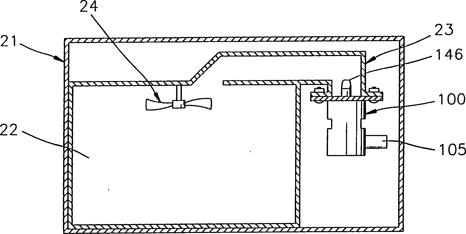
[0020] see image 3 , the microwave oven corresponding to the present invention includes a casing 21, a device 100 for generating microwaves, a power supply part 105 installed on the device 100, and a cooking chamber 22 for accommodating food. Microwave generating device 100 comprises filter box 101, and the bottom of filter box 101 is equipped with plate 102, and top is equipped with support 103 (see Figure 4 ).

[0021] see Figure 4 and Figure 5 , the filter box 101 is equipped with a heater 110 electrically connected to the power supply part 105 as a heating element, a cathode 120 , a first grid 130 , a second grid 140 and an anode 150 . Also, a vacuum is maintained inside the filter box 101 .

[0022] The heater 110 is formed of a filament, and the cathode 120 is disposed above the heater 110 . When the heater 110 is heated, the disk-shaped cathode 120 emits thermal electrons. A first grid 130 that can control and focus electrons emitted from the cathode 120 is di...


PUM


Abstract

A microwave oven, including a microwave generating device, the device includes: a cathode, a first grid, a flow-blocking structure, a resistor, a second grid, an anode and a main power supply; the cathode, the first grid and the flow-blocking structure form an input space The cavity, the second grid plate and the anode form an output cavity, which is electrically insulated from the input cavity; the main power supply device supplies power to the cathode and the anode. The flow blocking structure includes a grid support and a board, the inner and outer surfaces of the board are covered with metal films, and the board also has an insulating part.

Description

technical field [0001] The invention relates to a microwave oven, in particular to a microwave oven equipped with a microwave generating device with a simple structure. Background technique [0002] figure 1 The shown microwave oven includes a casing 1, a power supply part 2 with a high-voltage transformer (not shown) and a high-voltage capacitor (not shown), a cylindrical magnetron 10 that can generate microwaves, and a container that can hold food therein. Cooking chamber 3. Such as figure 2 As shown, the magnetron 10 is a cylindrical bipolar vacuum tube, generally including a cathode 11 arranged at the center thereof, a pair of magnets 12a, 12b respectively arranged above and below it, an anode 13 surrounding the cathode 11 and connected to the anode 13 Antenna 14 . [0003] When an operating voltage from the power supply section 2, for example, a voltage of 4KV, is applied to the input terminal 15, the cathode 11 is heated and electrons are emitted. The emitted ele...

Claims


Application Information

Patent Timeline
Patent Type & Authority Patents(China)
IPC IPC(8): H05B6/66H01J23/075H01J23/54H01J25/04
CPCH01J23/54H01J25/04
Inventor 郑利教
Owner DAEWOO ELECTRONICS CO LTD
Learn More