Carbon dioxide transcrisis refrigeration circulation rolling rotor energy recovery device

A technology of rolling rotor and carbon dioxide, which is applied in the direction of refrigerators, refrigeration components, refrigeration and liquefaction, etc., can solve the problems of difficult application, complex structure, expander machinery, etc., and achieve the advantages of safe operation, overcoming the starting dead point, and reducing noise Effect

Inactive Publication Date: 2005-06-29
TIANJIN UNIV
View PDF0 Cites 0 Cited by
  • Summary
  • Abstract
  • Description
  • Claims
  • Application Information

AI Technical Summary

Problems solved by technology

Using an expander instead of a throttle valve to recover the expansion work can increase the CO 2 system COP, but due to CO 2 The inlet of the expander is a supercritical fluid, and the currently studied CO 2 There are both mechanical and leakage losses in the expander, how to combine CO 2 Characterization of transcritical cycles through rational structural design to enhance CO 2 The efficiency of the expander has become a key issue that needs to be solved urgently to improve the COP
CO 2 The expander can output mechanical work, but it is rarely used. If it is coaxially connected with other energy-consuming equipment such as water pumps, fans, compressors, etc., it is difficult to realize due to problems such as complex structure and difficult speed control and matching.

Method used


Image

  • Carbon dioxide transcrisis refrigeration circulation rolling rotor energy recovery device
  • Carbon dioxide transcrisis refrigeration circulation rolling rotor energy recovery device
  • Carbon dioxide transcrisis refrigeration circulation rolling rotor energy recovery device

Examples


Embodiment Construction

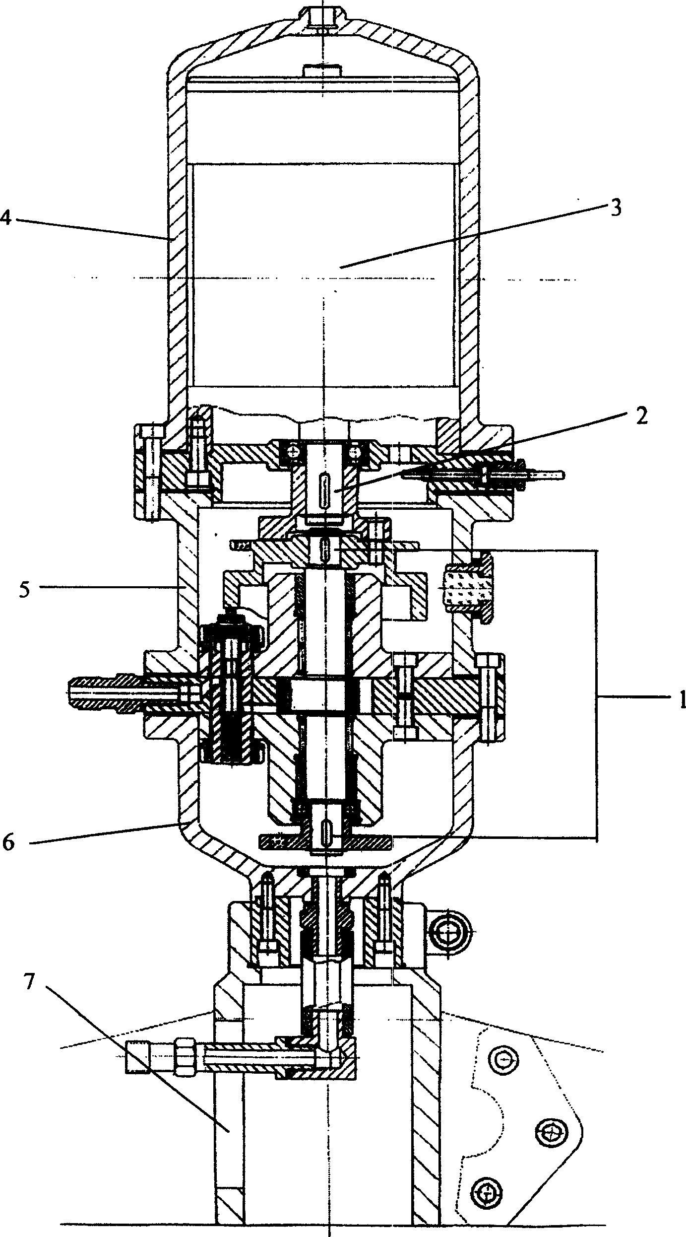
[0009] The arrangement of the present invention in the system is as attached Figure 5 The dashed box part in.

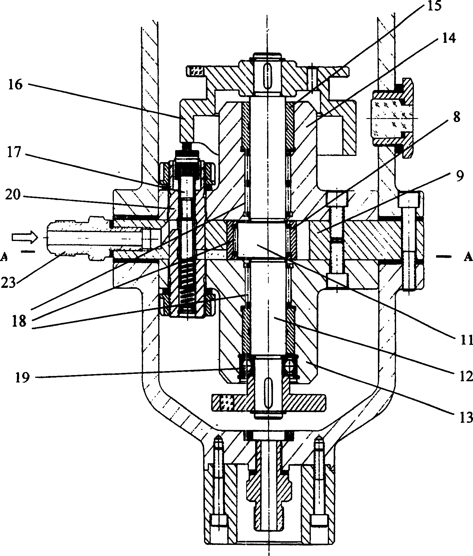
[0010] During installation, the inlet pipe 23 of the carbon dioxide transcritical refrigeration cycle rolling rotor energy recovery device (the present invention) is connected to the outlet of the gas cooler 30, and the outlet 24 is connected to the inlet of the evaporator 31. The main shaft 12 of the rolling rotor expander 1 is coaxially and vertically installed with the main shaft of the generator-motor 3 through a coupling 2. The electric energy output by the generator-motor 3 is used for the operation of the load, and the load can be a small electric device such as a water pump and a fan of the system.

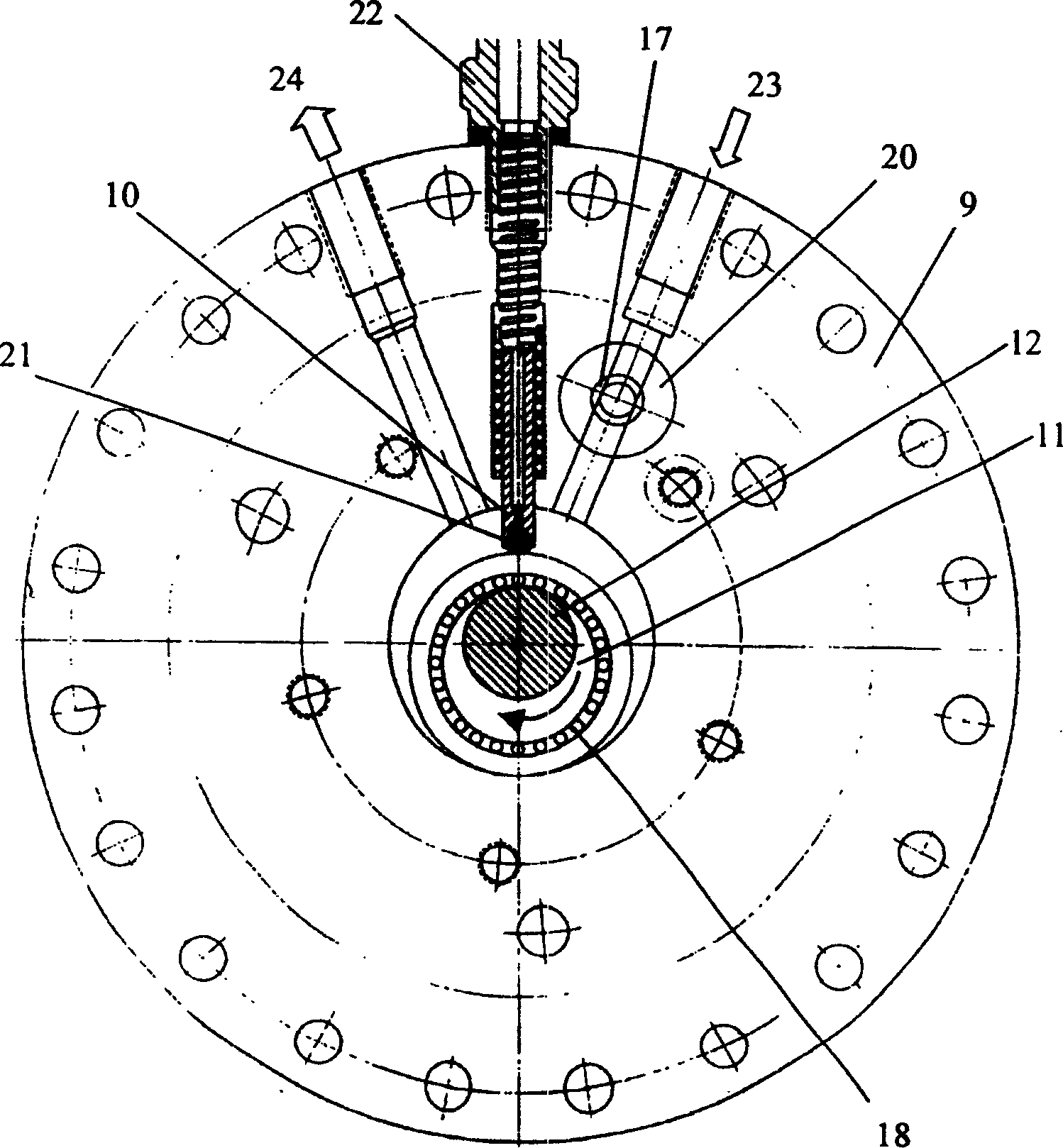
[0011] When working, press the normally open contact switch 27, the electric motor 26 of the generator-motor 3 starts, and drives the rolling rotor expander 1 to rotate in the direction shown in FIG. 3, which overcomes the starting dead point of the rolling rotor exp...


PUM


Abstract

The carbon dioxide transcritical refrigeration cycle rolling rotor energy recovery device is mainly composed of a rolling rotor expander, a generator-motor, a casing and a base, etc. The rolling rotor expander and the generator-motor are connected through a coupling. Among them, the rolling rotor expander, coupling and generator-motor are all encapsulated in the casing composed of upper, middle and lower casings. The valve stem below the cam disc is controlled by a cam disc line that rotates synchronously with the eccentric shaft. When the hole above the control stem is opposite the square hole in the seat, the CO 2 The fluid enters the expansion chamber, and the sliding plate rotates to expand and do work. When the present invention is started and running, the generator-motor is used as an electric motor to drive the main shaft of the expander to rotate, overcoming the dead point of the rotor expander; when the rotor expander is in operation, it is used as a generator to convert the output work of the rotor expander For the external output of electric energy. The invention can effectively recover the energy loss in the throttling process and improve the performance coefficient of the whole system.

Description

Technical field [0001] The invention belongs to an energy recovery device in refrigeration, air-conditioning and heating equipment. Background technique [0002] At present, the refrigerants commonly used in the refrigeration and air-conditioning industry are CFCs (chlorofluorocarbons) and HCFCs (hydrochlorofluorocarbons) substances. Because of their destructive effects on the ozone layer and the greenhouse effect, scientists around the world are intensively studying their alternative work. Among them, carbon dioxide has been re-introduced into the refrigeration heat pump industry with its excellent environmental protection characteristics, good heat transfer and flow properties. So in CO 2 Refrigerant is the preferred method to solve CFC replacement. However, to realize CO in industrial technology 2 There are still some difficulties in transcritical refrigeration cycles. The main reason is CO 2 Its throttling loss is larger than that of conventional working...

Claims


Application Information

Patent Timeline
Patent Type & Authority Patents(China)
IPC IPC(8): F25B9/00F25B9/06
CPCF25B9/008F25B9/06F25B2309/061
Inventor 马一太杨昭查世彤张云宪涂铭海苏维诚
Owner TIANJIN UNIV
Why Eureka
Try Eureka