Oil field produced water heat pump technique

A technology for producing water and heat pump, which is applied in the directions of heat pump, production fluid, earthwork drilling, etc., can solve the problems such as the temperature not reaching 80 °C, serious scaling, etc., and achieve the effect of improving COP and reducing fuel consumption.

Inactive Publication Date: 2009-01-14
王培军 +1
View PDF0 Cites 15 Cited by
  • Summary
  • Abstract
  • Description
  • Claims
  • Application Information

AI Technical Summary

Problems solved by technology

However, some problems have also been exposed: 1. The medium-temperature heat pump currently used cannot reach the temperature of 80°C required by the crude oil dehydration and crude oil export process; 2. The produced water used to protect the heat pump evaporator-clean water heat exchanger is fouled Serious; 3. The use of produced water-clean water heat exchanger has an additional temperature difference, so that the temperature entering the heat pump evaporator is only 35-42°C, which is 6-10°C lower than the produced water temperature; 4. The produced water-clean water heat exchange process requires long-term operation of the water pump and a corresponding water supply system; 5. Use the hot water of the water source heat pump to heat the crude oil, and use the oil-high-temperature clean water heat exchanger to make the final temperature of the crude oil higher than that of the condenser The outlet of medium and high temperature clean water is reduced by 6-10°C; 6. The process of condenser and oil-high temperature clean water heat exchanger requires long-term operation of the water pump

Method used


Image

  • Oil field produced water heat pump technique

Examples


Embodiment Construction

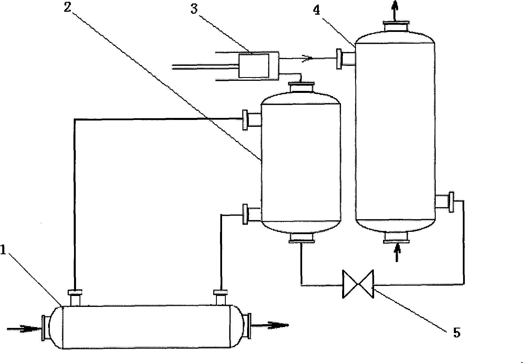
[0011] combined with figure 1 , the present invention is further described, comprising the following steps: the oil field produced water is sent to the tube side of the produced water boiling heat exchanger 1 from the sewage tank (generally, the gauge pressure of the tank is 0.06MPa), and the oil field produced water is discharged after cooling. Enter the produced water discharge pumping station pipeline: the shell side of the produced water boiling heat exchanger 1 is filled with low boiling point working fluid, which absorbs heat and vaporizes and enters the shell side of the heat pump working medium evaporator 2, releases heat and condenses into a liquid before flowing back to the produced water The shell side of the boiling heat exchanger 1: the heat pump working medium in the evaporator 2 tube is the heat pump working medium, which absorbs heat and vaporizes into steam, and sends the steam to the compressor 3 through the pipeline to increase the pressure and heat up; throu...


PUM


Abstract

The invention relates to an oilfield produced water heat pump which is used for heating of outward transported crude oil, dehydration of the crude oil and the heat pump process of oilfield produced water for heating. The technical proposal thereof is as follows: the oilfield produced water is sent to a tube pass of a boiling heat exchanger of the produced water from a sewage tank, the oilfield produced water enters a pipeline of an outer drainage pump station of the produced water after heat release and temperature decrease and then enters a shell pass of a working media evaporator of the heat pump after heat absorption and gasification, the released heat is condensed to liquid and then flows back to the shell pass of the boiling heat exchanger of the produced water, steam is sent to a compressor for increasing the pressure and the temperature; the steam is sent to the shell pass of the working media evaporator for releasing the heat and being condensed to the liquid through a pipeline, and the liquid is sent to the tube pass of the working media evaporator of the heat pump after the pressure decrease by a throttle valve; the crude oil or the heating circulating water which needs to be heated is passed in the tube pass of a working media condenser for absorbing the heat which is released by the working media condenser of the heat pump, thereby achieving the needed temperature for outward transportation. The oilfield produced water heat pump of the invention has the advantages that: the oilfield produced water heat pump reduces the fuel consumption and has no waste gas emission; the problems of corrosion resistance, scale resistance and great heat transfer temperature difference in the oilfield produced water heat energy application can be solved, and the COP of the heat pump is improved.

Description

1. Technical field: [0001] The invention relates to a process for utilizing low-grade heat energy, in particular to an oil field produced water heat pump process for heating exported crude oil, crude oil dehydration and heating. 2. Background technology: [0002] my country's energy consumption is dominated by coal and oil, and environmental problems have become increasingly prominent. It is the second largest energy consumer in the world. The resulting soot and sulfur dioxide emissions accounted for 70% and 90% of the country's total emissions, respectively, and the area of ​​acid rain formed by sulfur dioxide emissions has accounted for one-third of the country's land area. [0003] The National Development and Reform Commission requires strengthening research on energy-saving technologies, energy-saving theories and methods in the exploration, development, production, and construction of the onshore oil and gas industry. Reduce energy consumption in the process of oil an...

Claims


Application Information

Patent Timeline
Patent Type & Authority Applications(China)
IPC IPC(8): F25B30/06E21B36/00E21B43/34
Inventor 张洪山廉庆存周立超甄然王培军
Owner 王培军
Why Eureka
Try Eureka