Refrigeration system

a refrigeration system and compressor technology, applied in refrigeration components, refrigeration safety arrangements, light and heating equipment, etc., can solve the problems of increasing power consumption of compressors, reducing compressor power consumption, and evaporation temperature approaching the set temperature, so as to reduce compressor power consumption, reduce the coefficient of performance, and prevent the amount of heat exchange

Active Publication Date: 2011-02-03
DAIKIN IND LTD
View PDF5 Cites 17 Cited by
  • Summary
  • Abstract
  • Description
  • Claims
  • Application Information

AI Technical Summary

Benefits of technology

[0024]Unlike conventional refrigeration systems, according to the present invention, the set temperature Tem can be changed to a value larger than a current value based on the target superheat degrees SHs of the evaporators (27). Approaching of the evaporation temperature Te to the thus changed set temperature Tem can reduce power consumption of the compressor (21) as compared to power consumption before the change in the set temperature Tem, while preventing the amount of heat exchange in each of the evaporators (27) from decreasing from the amount before the change in the set temperature Tem. Accordingly, in the refrigeration system including the refrigerant circuit (20) with a plurality of evaporators (27), power consumption of the compressor (21) necessary for obtaining the amount of heat exchange in the evaporators (27) can be reduced as much as possible to reduce a decrease in the coefficient of performance (COP) of the refrigeration system.
[0025]The change in the set temperature Tem to a value larger than the current value increases the evaporation temperature Te and reduces the refrigerant outlet superheat degrees SH of the evaporators (27). As shown in FIG. 3, as the refrigerant outlet superheat degree SH decreases, the COP tends to increase. Thus, a decrease in the refrigerant outlet superheat degrees SH of the evaporators (27) can reduce power consumption of the compressor (21) as much as possible to reduce a decrease in the coefficient of performance (COP) of the refrigeration system.
[0026]In the second aspect, the amount of change in changing the set temperature Tem to a value larger than the current value can be determined based on a deviation between the minimum target superheat degree SHsm and the predetermined value SHt. Thus, power consumption of the compressor (21) necessary for obtaining the amount of heat exchange in the evaporators can be appropriately reduced according to the operating state of the refrigeration system, thereby reducing a decrease in the coefficient of performance of the refrigeration system.
[0027]In the third aspect, the amount of change determined by the determination part (5a) can be corrected based on the capacity of the evaporator (27) having the minimum target superheat degree SHsm. Thus, according to the capacity of the evaporator (27) having the minimum target superheat degree SHsm, the power consumption of the compressor (21) can be more appropriately reduced to reduce a decrease in the coefficient of performance of the refrigeration system.
[0028]In the fourth aspect, even the refrigeration system including the refrigerant circuit (20) in which carbon dioxide is enclosed, power consumption of the compressor (21) necessary for obtaining the amount of heat exchange in the evaporators (27) can be reduced as much as possible to reduce a decrease in the coefficient of performance of the refrigeration system. In addition, if the refrigeration system of this aspect is configured such that the set temperature Tem is gradually changed to larger values from the current value, i.e., is gradually increased from the current value, and when the minimum target superheat degree SHsm reaches the predetermined value SHt or less, the change in the set temperature Tem is stopped, thus enabling control of the target superheat degrees SHs of the evaporators (27). Accordingly, in the case where the degree of a decrease in the COP with an increase in the refrigerant outlet superheat degree SH is higher than that in the case of using a fluorocarbon refrigerant, as in a refrigeration system using carbon dioxide, control for preventing an increase in the refrigerant outlet superheat degree SH can reduce a decrease in the coefficient of performance of the refrigeration system.

Problems solved by technology

Then, power consumption of the compressor decreases, and the evaporation temperature increases, resulting in that the evaporation temperature approaches the set temperature.
Then, power consumption of the compressor increases, and the evaporation temperature decreases, resulting in that the evaporation temperature approaches the set temperature.

Method used


Image

  • Refrigeration system
  • Refrigeration system
  • Refrigeration system

Examples


Embodiment Construction

[0061]An embodiment of the present invention will be specifically described hereinafter with reference to the drawings.

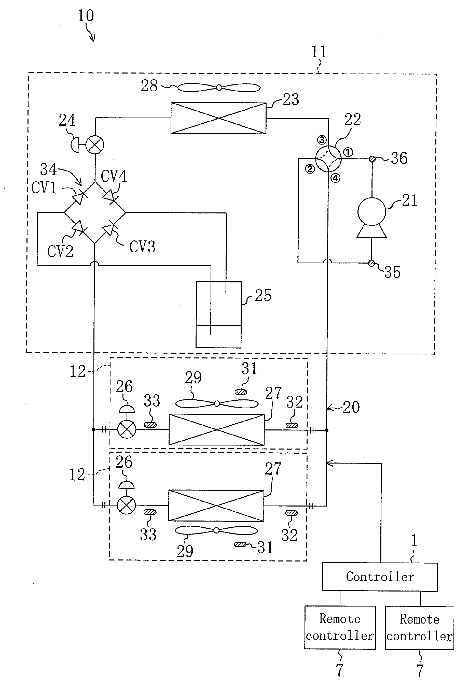
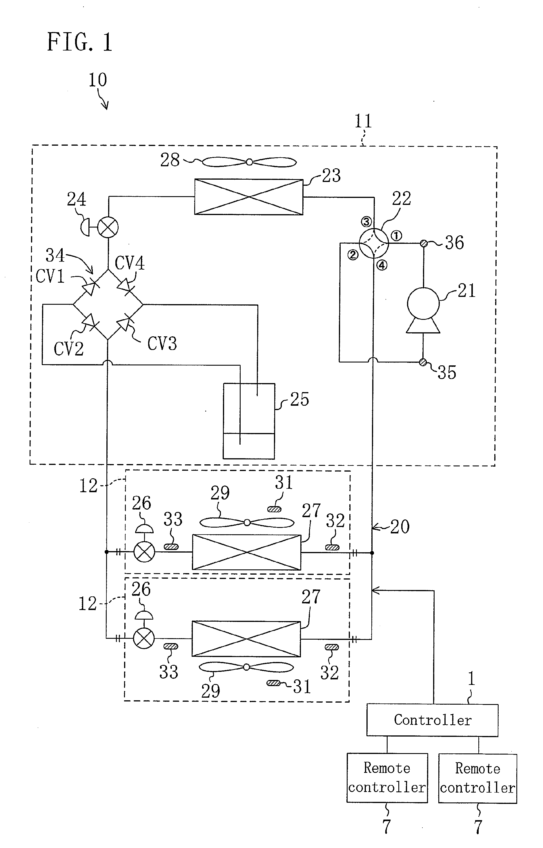
[0062]FIG. 1 is a refrigerant circuit diagram illustrating an air conditioner according to this embodiment. The air conditioner (a refrigeration system) (10) of this embodiment is a multi-type air conditioner including an outdoor unit (11) and a plurality of indoor units (12), and can perform cooling operation and heating operation. The outdoor unit (11) is placed outdoors, and each of the indoor units (12) is placed in an indoor space. As illustrated in FIG. 1, the air conditioner (10) includes a refrigerant circuit (20), a controller (1), and remote controllers (7) associated with the respective indoor units (12).

[0063]

[0064]The refrigerant circuit (20) is a closed circuit using carbon dioxide as a refrigerant, and is configured to perform a supercritical refrigeration cycle in which the high pressure of the refrigerant circuit (20) is set at a pressure higher tha...


PUM


Abstract

An air conditioner (10) includes a refrigerant circuit (20) including a plurality of indoor heat exchangers (27). A controller (1) for controlling operation of the air conditioner (10) includes a change unit (5) configured to change a set temperature Tem to a value larger than a current value when the minimum target superheat degree SHsm of target superheat degrees SHs determined for the respective indoor heat exchangers (27) is higher than a predetermined value SHt.

Description

TECHNICAL FIELD[0001]The present disclosure relates to refrigeration systems including refrigerant circuits performing refrigeration cycles, and more particularly to techniques for controlling operation of a refrigeration system including a refrigerant circuit in which a plurality of evaporators are connected to each other.BACKGROUND ART[0002]Conventional refrigeration systems including refrigerant circuits performing refrigeration cycles by circulating refrigerants are known. Examples of such refrigeration systems include a so-called multi-type refrigeration system in which a plurality of indoor units are connected in parallel to one outdoor unit (see, for example, Patent Document 1).[0003]In this refrigeration system, the outdoor unit includes an outdoor circuit, and the indoor units include indoor circuits. The outdoor circuit includes a compressor, an outdoor heat exchanger, an outdoor expansion valve, and a receiver, for example. Each of the indoor circuits includes an indoor h...

Claims


Application Information

Patent Timeline
Patent Type & Authority Applications(United States)
IPC IPC(8): F25B1/00
CPCF25B9/008F25B13/00F25B2309/061F25B2313/0233F25B2313/0272F25B2313/02741Y02B30/741F25B2600/21F25B2600/2513F25B2700/21171F25B2700/21174F25B2700/21175F25B2600/021Y02B30/70
Inventor KASAHARA, SHINICHI
Owner DAIKIN IND LTD
Why Eureka
Try Eureka