
Magnetic attracted plane reflective mirror optical valves

A flat mirror and magnetic adsorption technology, applied in the coupling of optical waveguides, can solve problems such as difficult assembly, high insertion loss, and increased difficulty in installation and manufacturing, and achieve the effects of not easy to wear, high repeatability, and avoiding position changes

Inactive Publication Date: 2005-07-06
SHANGHAI INST OF OPTICS & FINE MECHANICS CHINESE ACAD OF SCI
View PDF1 Cites 0 Cited by
  • Summary
  • Abstract
  • Description
  • Claims
  • Application Information

AI Technical Summary

Problems solved by technology

The disadvantage of this optical switch is that the limit mechanism is complicated, which increases the difficulty of installation and manufacture, and the repeatability is poor (0.2dB).
Another example: Chinese patent "a kind of mechanical optical switch" (patent number: CN2446528Y, publication date: September 5, 2001), the outgoing and incident optical fiber collimators of this optical switch are all at one end, and the collimator and the fixed A prism is arranged between the reflectors, and the movable reflector is arranged between the fixed prism and the fixed reflector, and is fixed on the connecting rod connected with the current collector, and the method of positioning the movable reflector by means of the bearing, through the current collector switch and the corresponding The rotating device realizes the movement of the movable reflector, thereby changing the optical path and realizing multi-channel optical switch. The disadvantage of this optical switch is that the light beam needs to be coupled through the prism and the reflector, resulting in high additional insertion loss. The mechanism drives the plane reflector to switch the optical path, the mechanical structure is more complex, the repeatability is poor, and there is no self-locking function, the power consumption is high, and it is difficult to assemble when forming a multi-channel optical switch

Method used

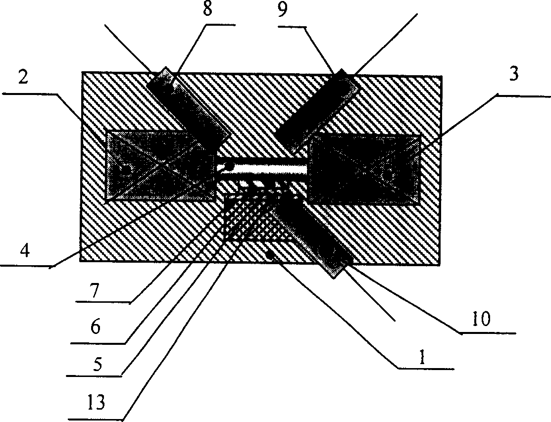

Image

  • Magnetic attracted plane reflective mirror optical valves
  • Magnetic attracted plane reflective mirror optical valves
  • Magnetic attracted plane reflective mirror optical valves

Examples


Embodiment Construction

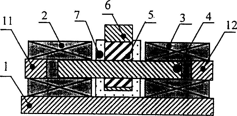
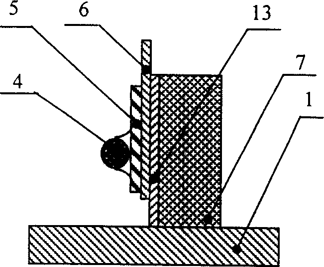
[0020] see first figure 1 and figure 2 , The optical switch of the magnetic adsorption planar mirror of the present invention includes four parts: a substrate, an optical path coupling, a magnetic adsorption holding and an electromagnetic drive. The optical path coupling part is made up of the first fiber collimator 8, the second fiber collimator 9, the third fiber collimator 10 and the plane mirror 6; the magnetic adsorption holding part includes a fixed soft magnet 7, quartz glass 13 and The movable permanent magnet 5 ; the electromagnetic drive part includes a first electromagnetic coil 2 , a second electromagnetic coil 3 , a moving shaft 4 , a first limiting block 11 and a second limiting block 12 . The latter three parts are all fixed on the base plate 1, and the base plate 1 is made of super duralumin material.

[0021] Such as figure 2 As shown, the first electromagnetic coil 2 and the second electromagnetic coil 3 of the electromagnetic drive part are symmetricall...


PUM


Abstract

The invention discloses an optical switch of a magnetic adsorption plane reflector, which realizes the switching of the optical path through the method of translating the plane reflector. Using the high-precision positioning technology of the magnetic adsorption plane mirror, the magnetic force of the permanent magnetic field is applied in the direction orthogonal to the reflection surface of the plane mirror, so that the plane mirror is adsorbed on a fixed reference plane, ensuring that the plane mirror The reflective surface of the reflector is always on the same plane whether it is in the dynamic process or in the static state; the push-pull electromagnetic drive method is used to translate the plane reflector, so that the plane reflector can be inserted into or withdrawn from the optical path to realize the switching of the optical path, forming a 1× 2 or 2×2 mechanical optical switches. The optical switch has the characteristics of self-locking function, low power consumption, short switching time, high positioning accuracy, good repeatability, long working life, simple structure and easy production and assembly.

Description

Technical field: [0001] The invention relates to a mechanical optical switch, in particular to a high-precision positioning magnetic adsorption plane mirror optical switch. Background technique: [0002] The core technology of the new-generation all-optical network is all-optical switching, and the optical switch is a key device in all-optical switching, which is mainly used to implement functions such as routing selection at the all-optical layer, optical cross-connection, and self-healing protection. There are also a large number of applications in optical measurement and so on. As far as the current situation of optical switches is concerned, they are classified according to the switching mechanism, mainly including mechanical optical switches, thermo-optical switches and electro-optical switches. Compared with other types of optical switches, mechanical optical switches have better performance in terms of insertion loss, isolation, extinction ratio, and polarization sen...

Claims


Application Information

Patent Timeline
Patent Type & Authority Patents(China)
IPC IPC(8): G02B6/26G02B6/35
Inventor 董作人陈高庭方祖捷耿建新
Owner SHANGHAI INST OF OPTICS & FINE MECHANICS CHINESE ACAD OF SCI
Learn More