Biosensor

a biosensor and sensor technology, applied in the field of biosensors, can solve the problems of unstable layer form, slow enzyme reaction, difficult to improve measurement precision,

Inactive Publication Date: 2005-07-12
ARKRAY INC
View PDF17 Cites 123 Cited by
  • Summary
  • Abstract
  • Description
  • Claims
  • Application Information

AI Technical Summary

Benefits of technology

[0009]Therefore, it is an object of the present invention to provide a biosensor that can measure an object to be measured in a sample rapidly and simply with high precision without being affected by the impurities in the sample.
[0031]In the biosensor of the present invention, it is preferable that a surfactant-containing layer containing a surfactant is further formed on the reagent layer. If the surfactant-containing layer is provided in this manner, a hydrophilic film is formed on the surface of the reagent layer, so that the sample and the reagent can be mixed quickly and uniformly. Consequently, a reaction proceeds rapidly, and the repeatability can be improved.

Problems solved by technology

In this biosensor, the problem with the filtering film is solved, but since a water-soluble high molecular weight compound is used, the water absorptivity is high so that the biosensor is susceptible to humidity, which causes problems in that the enzyme reaction is slow or the form of the layer is unstable.
Therefore, it is difficult to improve measurement precision, and measurement takes time.

Method used


Image

  • Biosensor
  • Biosensor
  • Biosensor

Examples


embodiment 1

(Embodiment 1)

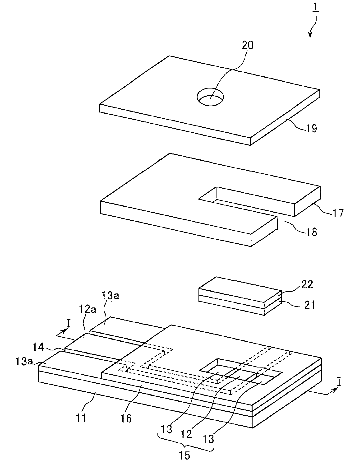
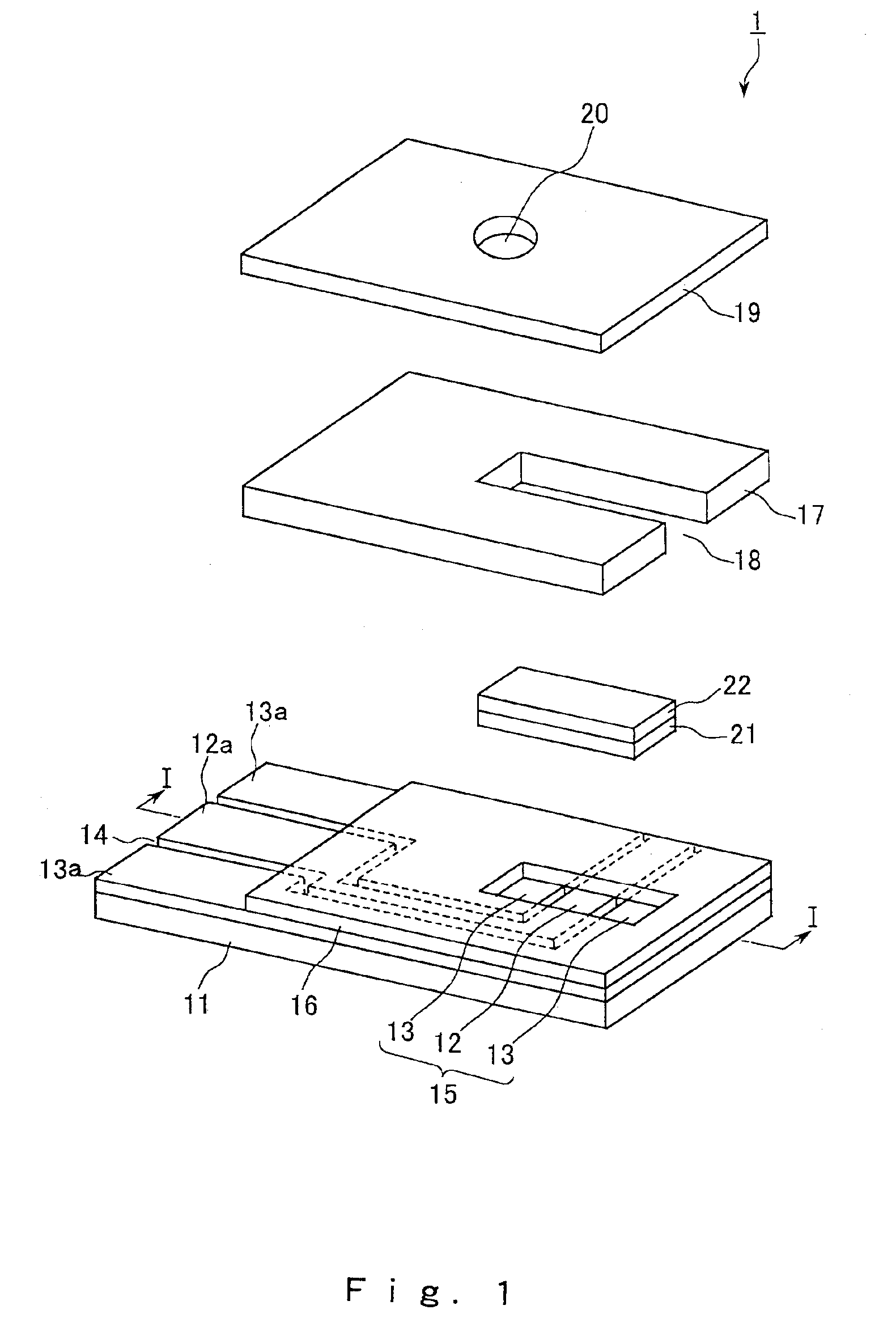
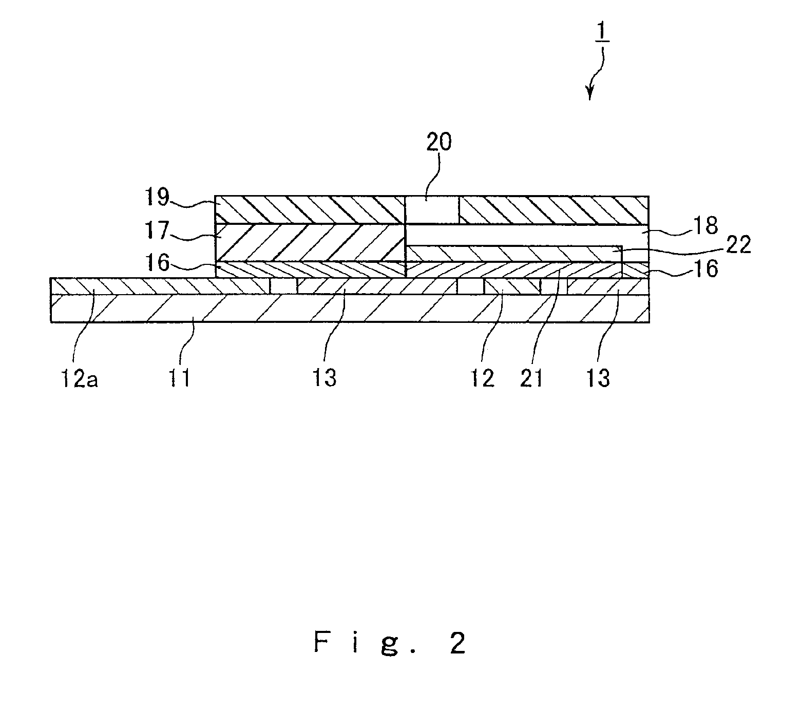
[0044]FIGS. 1 and 2 show an example of a biosensor of the present invention. FIG. 1 is a perspective view schematically showing the biosensor, and FIG. 2 is a cross-sectional view taken along line I—I of FIG. 1.

[0045]As shown in the drawings, this biosensor 1 includes a substrate 11, an electrode system including a working electrode 12 having a lead portion 12a and two counter electrodes 13 having lead portions 13a, a particulate-containing layer 21, a reagent-containing layer 22, a spacer 17, and a cover 19. A detecting portion 15 is provided on one end portion (on the right side of FIGS. 1 and 2) of the substrate 11, and the two counter electrodes 13 and the working electrode 12 are alternately disposed parallel with the width direction of the substrate 11 on the detecting portion 15. The electrodes drawn out from the detecting portion 15 are disposed on the substrate 11 in such a manner that the electrodes are bent before reaching the lead portions 12a and 13a of th...

embodiment 2

(Embodiment 2)

[0087]This embodiment is an example of the biosensor of the present invention having a surfactant-containing layer on the reagent-containing layer. FIG. 3 is a cross-sectional view of this biosensor. In FIG. 3, the same components as those in FIG. 2 bear the same reference numeral.

[0088]As shown in FIG. 3, the biosensor 3 has the same structure as in Embodiment 1, except that a surfactant-containing layer 31 is laminated on the reagent-containing layer 22. Thus, if the surfactant-containing layer 31 is provided, not only can the sample and the reagents be mixed rapidly and uniformly, but also the sample liquid in the capillary structure can be drawn in more rapidly and more reliably.

[0089]The content of the surfactant in the surfactant-containing layer 31 can be determined as appropriate, depending on the type or the amount of the sample to be supplied, the type of the surfactant or the like.

[0090]The surfactant-containing layer 31 can be formed by, for example, prepar...

example 1

[0091]A biosensor for measuring glucose having the same structure as that shown in FIG. 3 was produced in the following manner.

[0092]First, a PET sheet (manufactured by Toray Industries. Inc.) was prepared as the substrate 11, and a carbon electrode system including a working electrode and counter electrodes, each of which had a lead portion, was formed on one surface thereof. The carbon electrodes were formed by patterning by screen printing.

[0093]Next, an insulating resin polyester was dissolved in the solvent carbitol acetate so that the concentration was 75 wt % to prepare insulating paste, and the insulating paste was screen-printed on the electrode system. The printing was performed under the conditions: 300 mesh screen; and a squeegee pressure of 40 kg, and the amount used for the printing was 0.002 mL per cm2 of the electrode area. Printing was not performed on the detecting portion 15 and the lead portions 12a and 13a. Then, a heat treatment was performed, and thus the insu...


PUM

PropertyMeasurementUnit
thicknessaaaaaaaaaa
particle diameteraaaaaaaaaa
thicknessaaaaaaaaaa

Abstract

A biosensor is constituted by disposing an electrode system including a working electrode and a counter electrode on a substrate, forming an inorganic particulate-containing layer containing inorganic particulates thereon, and forming a reagent layer containing a reagent thereon. The inorganic particulates make it possible to prevent impurities in a sample from being in contact with the electrode system and being adsorbed therein, so that measurement is performed with high precision. The inorganic particulate-containing layer can be formed by applying a dispersion system of inorganic particulates and drying them, and it is preferable that the inorganic particulates are contained in the form of aggregates.

Description

[0001]This application is the national stage under 35 U.S.C. 371 of PCT / JP00 / 08029, which was filed on Nov. 14, 2000.TECHNICAL FIELD[0002]The present invention relates to a biosensor for electrochemically measuring a specific component in a sample liquid such as blood.BACKGROUND ART[0003]Biosensors that can quantify a specific object to be measured in a sample liquid in a simple and rapid manner, for example, without diluting or stirring the sample liquid have been used widely. Such a biosensor can be produced by, for example, forming an electrode system having a working electrode (also referred to as “measuring electrode”) and a counter electrode on an electrically insulating substrate by a method such as screen printing, and forming a reactive layer including a redox (oxidation-reduction) enzyme and an electron-accepting substance that react with the objective to be measured thereon. When the reactive layer is in contact with the sample liquid containing the object to be measured,...

Claims


Application Information

Patent Timeline
Patent Type & Authority Patents(United States)
IPC IPC(8): C12Q1/00
CPCC12Q1/001
Inventor KATSUKI, KOJIHAMAMOTO, KATSUMIYAGI, YUJIFUKUOKA, TAKAO
Owner ARKRAY INC
Why Eureka
Try Eureka