Eureka AIR delivers breakthrough ideas for toughest innovation challenges, trusted by R&D personnel around the world.

Bed frame being able to stretch and airbed using the frame

A telescopic frame, air bed technology, applied in the direction of bed frame, application, household appliances, etc., can solve problems such as affecting practicality, increasing weight, and heavy bed weight.

Inactive Publication Date: 2005-08-10
王正宗
View PDF0 Cites 0 Cited by
  • Summary
  • Abstract
  • Description
  • Claims
  • Application Information

AI Technical Summary

Problems solved by technology

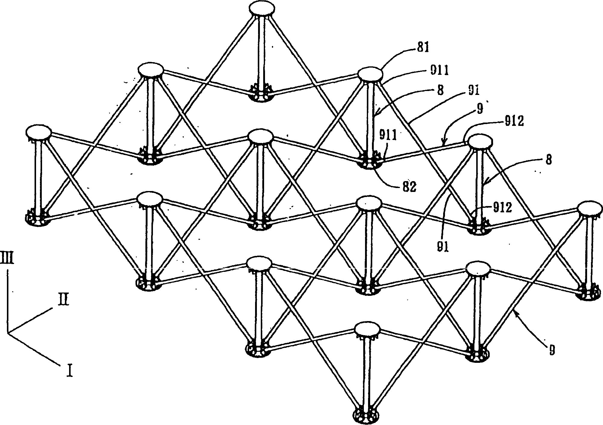
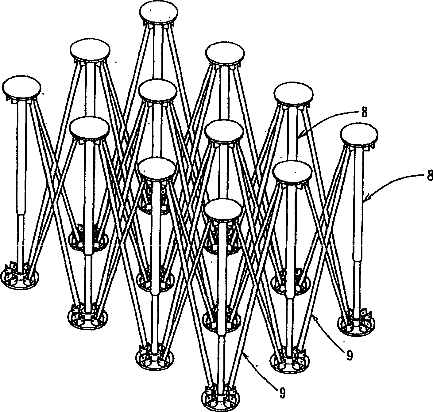
[0005] However, with respect to this kind of bed frame structure that can be opened and closed, since the bed frame must have a certain support stability, when in use, the distance between adjacent support bars 8 cannot be too large, otherwise the bed frame will be damaged. The body forms a sinking situation between two adjacent support rods 8, so once the bed body area is larger, the more support rods 8 are needed, and the more telescopic frames 9 are relatively. Made of light aluminum alloy, but once the number of bed frame components increases, the overall weight will inevitably increase, resulting in the situation that the larger the bed body, the heavier the weight, making it more difficult to carry, which greatly affects the practicality sex

Method used


Image

  • Bed frame being able to stretch and airbed using the frame
  • Bed frame being able to stretch and airbed using the frame
  • Bed frame being able to stretch and airbed using the frame

Examples


Embodiment Construction

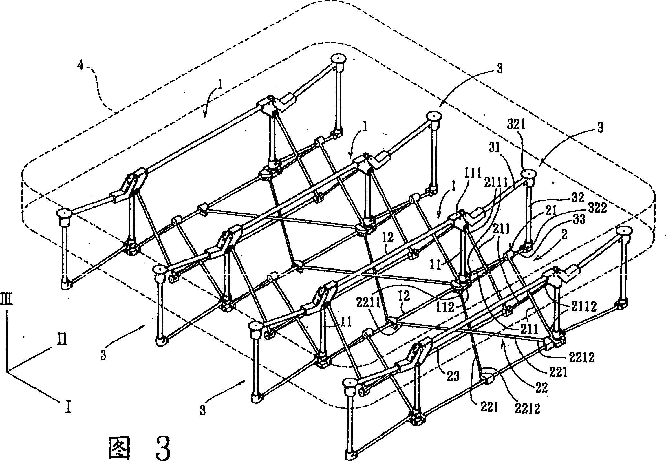
[0027] Referring to FIG. 3 , FIG. 4 and FIG. 5 , a preferred embodiment of the telescopic bed frame of the present invention includes several support units 1 , several telescopic units 2 , and several auxiliary support units 3 . The integral bed frame is also positioned on a supporting surface such as the ground to support a bed body 4 .

[0028] Each supporting unit 1 is parallel and juxtaposed along the telescopic direction of an I axis. In this example, the supporting unit 1 includes two upright rods 11 and two cross bars 12 connected to the upright rods 11, so that each supporting unit 1 is roughly in the shape of a square, But this form is not certain, if only a single cross bar 12 is used, it can become U-shaped, H-shaped or ㄩ-shaped. A first abutting portion 111 is formed at the top portion, and a first seating portion 112 is formed at the other end portion below the upright rod 11 close to the supporting surface. In addition, the upright pole 11 has a telescopic struc...


PUM


Abstract

An extendible bedstand is composed of several supporting units, several extendible unit and several auxiliary supporting units, all of which are parallelly and alternatively pivoted. An inflatable mattress for said bed stand is also disclosed.

Description

(1) Technical field [0001] The invention relates to a telescopic bed frame and an air bed using the telescopic bed frame. (2) Background technology [0002] figure 1 and figure 2 An existing bed frame with expandable and retractable functions is described. The bed frame includes several support rods 8 arranged side by side along the I-axis direction and the II-axis direction and an array of telescopic frames 9 connecting adjacent support rods 8, while the support rods 8 are upright along the III-axis direction and have the function of being able to stretch up and down. , so that the upper and lower ends of each support rod 8 are respectively covered with a plastic part to form a top 81 and a seat part 82 respectively. The top 81 is used to support a bed body (not shown). In addition, the telescopic frame 9 is formed in an X shape by two equal-length connecting rods 91, which are pivotally connected at the center so that the two connecting rods 91 can rotate relative to e...

Claims


Application Information

Patent Timeline
Patent Type & Authority Patents(China)
IPC IPC(8): A47C19/04A47C27/08
CPCA47C19/126A47C19/14
Inventor 王正宗
Owner 王正宗
Why Eureka
Eureka Blog
Learn More