Dielectric barrier discharge lamp

A dielectric barrier, discharge lamp technology, applied in the manufacture of discharge lamps, gas discharge lamps, discharge tubes/lamps, etc., to achieve the effect of cheap glass fusion

Inactive Publication Date: 2005-08-31
PATENT TREUHAND GESELLSCHAFT FUER ELECTRIC GLUEHLAMPEN M B H
View PDF2 Cites 0 Cited by
  • Summary
  • Abstract
  • Description
  • Claims
  • Application Information

AI Technical Summary

Problems solved by technology

The disadvantage is that a glass solder layer is required as a gas-tight connection between the stopper and the container wall

Method used


Image

  • Dielectric barrier discharge lamp
  • Dielectric barrier discharge lamp
  • Dielectric barrier discharge lamp

Examples


Embodiment Construction

[0030] figure 1 to 3 are used to illustrate the dielectric barrier layer-discharge lamp manufacturing method of the present invention.

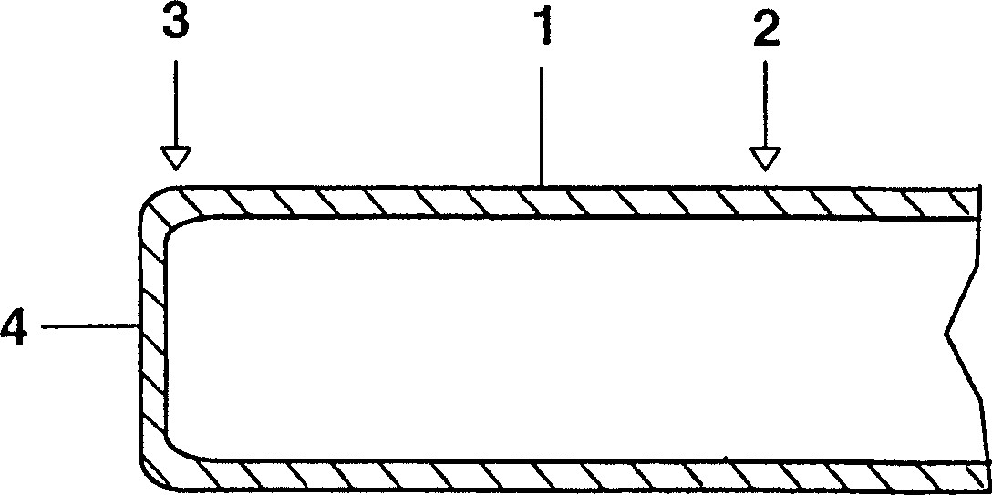
[0031] figure 1 A discharge vessel 1 made of soda-lime glass is shown, which is temporarily still open at a first end 2, but whose second end 3 has been sealed with a flat frit 4.

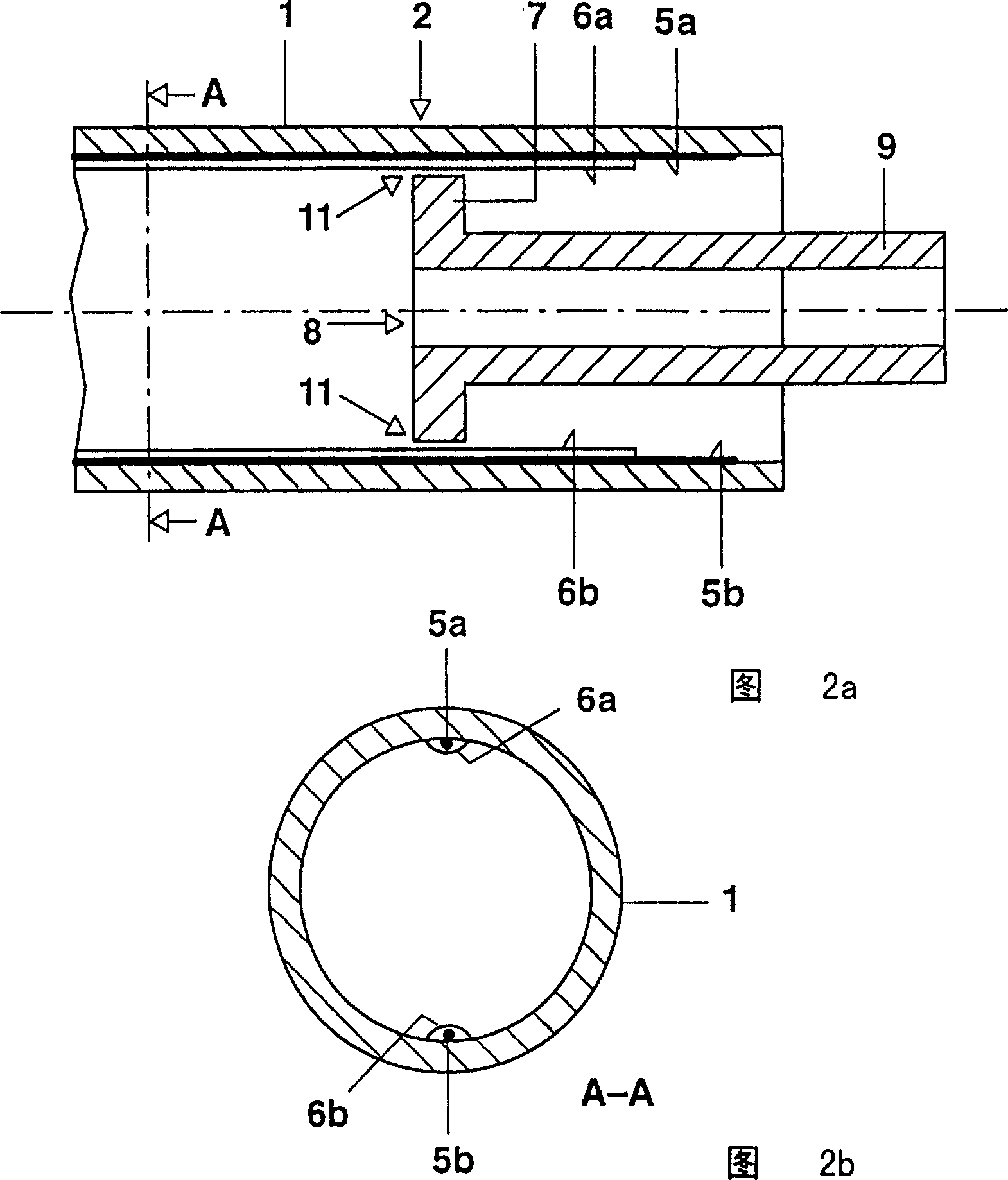
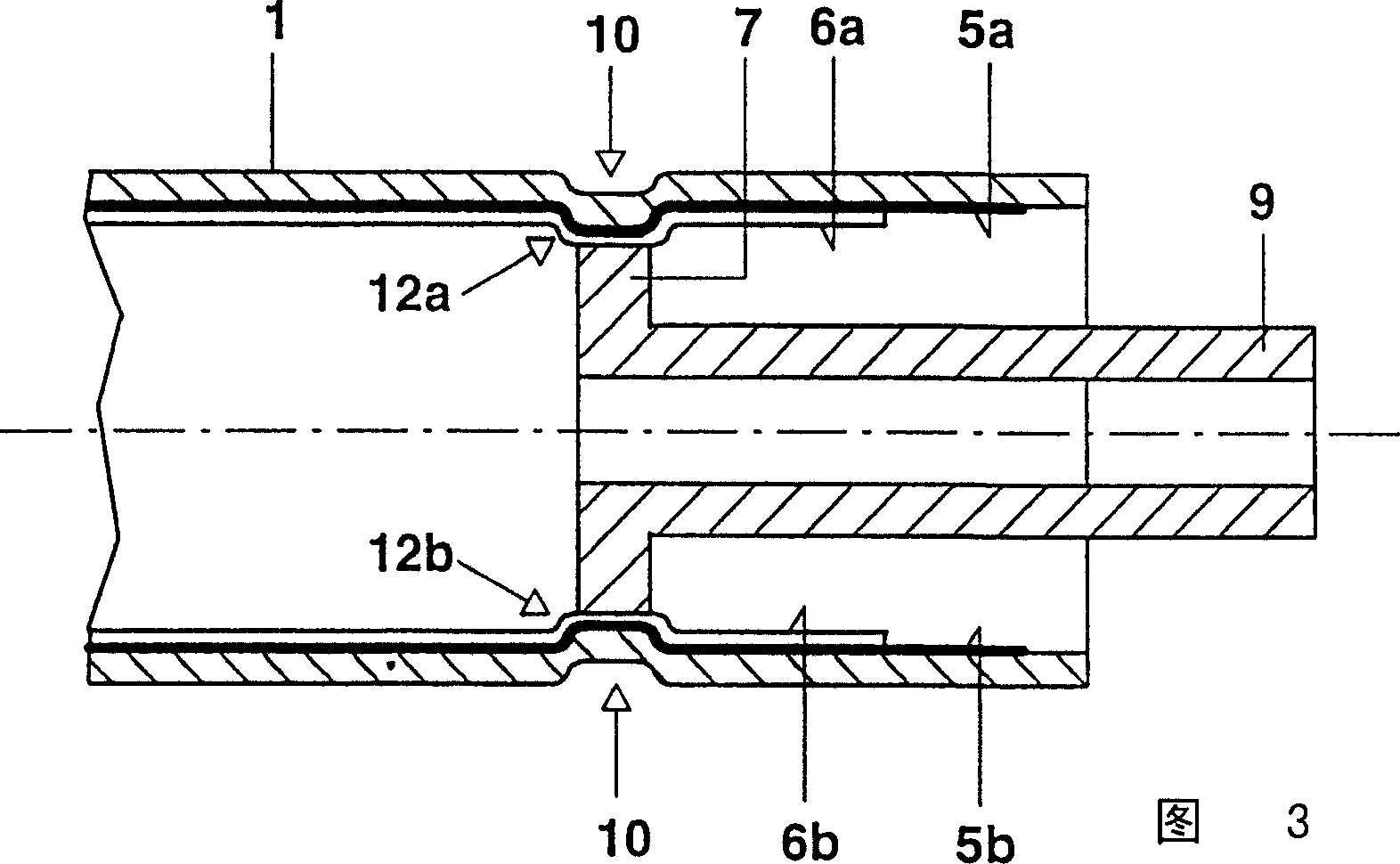
[0032] 2a, 2b respectively show a schematic longitudinal section of the open end 2 of the discharge vessel 1 and a schematic cross section along the section line A-A. The inner wall of the discharge vessel 1 has been provided with two radially arranged linear silver inner electrodes 5a, 5b which are each covered with a dielectric glass barrier layer 6a, 6b. Furthermore, a disc-shaped sealing element 7 has been arranged concentrically in the open end 2 of the discharge vessel 1 . The outer diameter of the disk-shaped sealing element 7 is slightly smaller than the inner diameter of the discharge vessel minus the thickness of the two inner electrodes 5a, 5b includ...


PUM


Abstract

The discharge tube (1) of a dielectric barrier discharge lamp is closed in gas-tight manner, without the use of a connecting means, by means of a plate-shaped closure element (7). To this end, the discharge tube (1) has a constriction (10), which encircles the edge of the plate-shaped closure element (7) in an annular manner.

Description

technical field [0001] The invention relates to a discharge lamp with a dielectric barrier. Background technique [0002] This is a discharge lamp in which either the electrodes of one polarity or all electrodes, ie both polarities, are separated from the discharge by a dielectric layer (so-called one- or two-sided dielectric barrier discharge). Such electrodes are also referred to below simply as "dielectric electrodes". The polarity of the electrodes can also be completely changed during operation, that is, each electrode can be used as an anode or cathode alternately. Of course, preferably all electrodes have a dielectric barrier. Further details can be found in document EP 0733 266 B1, which describes a dielectric barrier-discharge lamp. [0003] The above-mentioned dielectric layer can be formed by the wall of the discharge vessel itself, in which case the electrodes are arranged outside the discharge vessel, ie approximately on the outer wall. On the other hand, th...

Claims


Application Information

Patent Timeline
Patent Type & Authority Patents(China)
IPC IPC(8): H01J9/26H01J9/40H01J61/36H01J65/00H01J65/04
CPCH01J9/266H01J9/40H01J65/046H01J61/363H01J9/26
Inventor W·伯林霍夫R·贝尔勒G·德尔
Owner PATENT TREUHAND GESELLSCHAFT FUER ELECTRIC GLUEHLAMPEN M B H
Why Eureka
Try Eureka