Device for drop foot

A technology for foot and matching parts, which is applied in the field of devices for sagging feet, can solve the problems of poor lateral support, increase uncertainty, reduce the effect of spring on foot support, etc., and achieve the effect of light weight

Inactive Publication Date: 2005-10-12
埃罗·蒂卡拉
View PDF3 Cites 0 Cited by
  • Summary
  • Abstract
  • Description
  • Claims
  • Application Information

AI Technical Summary

Problems solved by technology

In the solution of US patent 4651723, the slip connection to the front part of the leg increases the uncertainty of the operation of the device and reduces the support effect of the spring on the foot
In particular, t

Method used


Image

  • Device for drop foot
  • Device for drop foot
  • Device for drop foot

Examples


Embodiment Construction

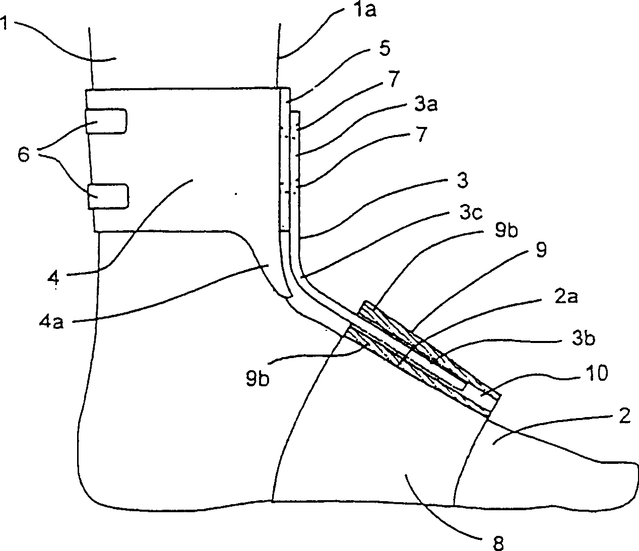
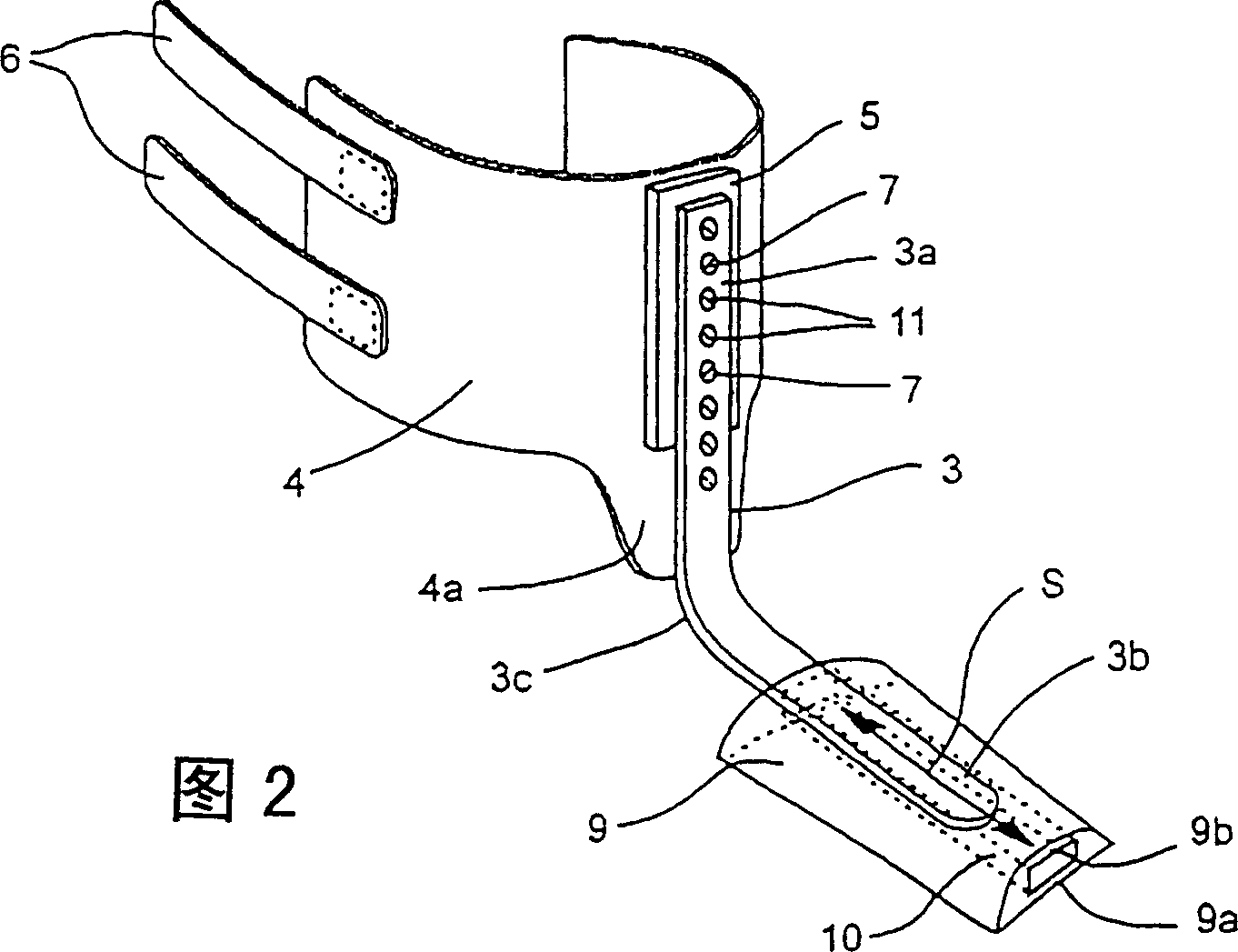
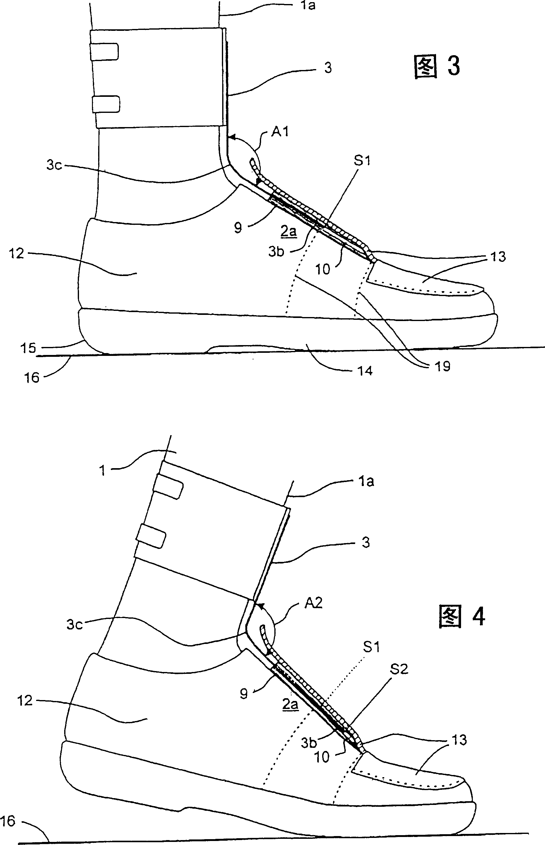
[0019] figure 1 The device in and 2 comprises a common strap 4 for fastening to the leg 1 . Corresponding positions of the narrow band 6 and the cuff are provided with, for example, Velcro pull straps, so the cuff can be easily adjusted according to the thickness of the legs, and can be properly tightened. The front part 4a of the cuff 4 is extended in order to protect the ankle from possible compression of the ankle by the spring 3 . The device proposed by the present invention has the advantage over some other devices that the most suitable fastening position of the cuff to the leg is the lowest part of the leg just above the ankle, which is usually the thinnest part of the leg. Partly, here, the cuff holds its position properly without strong tightening.

[0020] A plate 5 , for example made of suitable metal, is attached to a strap on the frontal part of the leg for securing the spring 3 . At the upper end 3a of the spring there are a number of holes 11 next to each oth...


PUM


Abstract

A device for drop foot is characterized in that the joint to the foot (2) of a spring (3) attached to the front side (1a) of a wearer's leg (1) includes an engagement piece (9, 10) attached in the instep area of the foot in which easy sliding of the spring in the longitudinal direction (S1, S2) thereof is allowed. The device allows easy angular bending of the foot against the force of the spring during walking. The foot is also easily returning back to the resting position thereof at an essentially right angle in relation to the leg. Abrasion of the foot, instep or ankle is essentially prevented. Footwear is easy to provide for use of the device of the invention without any uncomfortable accessories inside the footwear.

Description

technical field [0001] The present invention relates to a device for a dropped foot, and more particularly to a device of the type comprising longitudinally curved springs for supporting the ankle portion of the dropped foot, the springs being fixed respectively to the frontal part of the leg and the instep region of the foot . [0002] In the case of spinal cord injuries in particular, the resulting usual condition is a dysregulation of the gastrocnemius muscle (paresis peronei), which means that the ankle does not have the function to lift the foot, ie the foot is drooping. Without a mechanism to lift the foot or hold it at a right angle, walking is nearly impossible for a person afflicted with this disorder. Background technique [0003] In the simplest device for a dropped foot, there is a stem portion secured to the leg and another portion for supporting the sole of the foot, these holding the ankle at a substantially right angle. The stem portion is placed on the bac...

Claims


Application Information

Patent Timeline
IPC IPC(8): A61F5/01
CPCA61F5/0113
Inventor 埃罗·蒂卡拉
Owner 埃罗·蒂卡拉
Why Eureka
Try Eureka