General purpose combined harvester and thresher

A combine harvester and machine body technology, applied in the direction of harvesters, applications, cutters, etc., can solve the problems of body tilt left and right, complex conveying structure, weight increase, etc., to shorten the front and rear length, realize power consumption, and improve access Effect

Inactive Publication Date: 2005-11-16
YANMAR CO LTD
View PDF0 Cites 0 Cited by
  • Summary
  • Abstract
  • Description
  • Claims
  • Application Information

AI Technical Summary

Problems solved by technology

Therefore, the weight balance on the left and right is different between the beginning of the operation and the end of the operation, so it feels bad to operate the filling. When the threshing surface is soft, the body may tilt left and right, and the cutting height may be different from the left and right.
[0013] In order to discharge the grains in the fine-grain bin, it is necessary

Method used


Image

  • General purpose combined harvester and thresher
  • General purpose combined harvester and thresher
  • General purpose combined harvester and thresher

Examples


Embodiment Construction

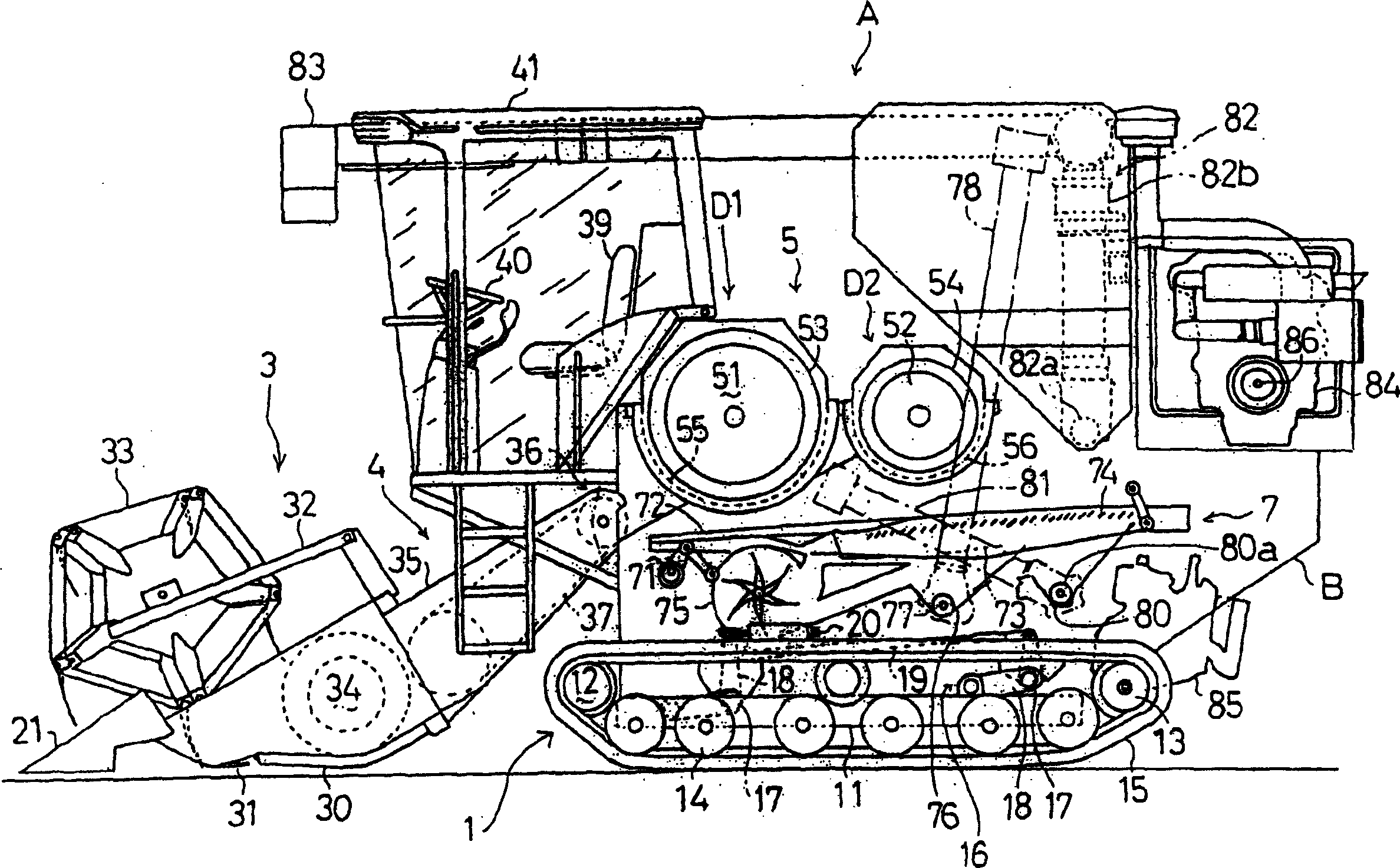
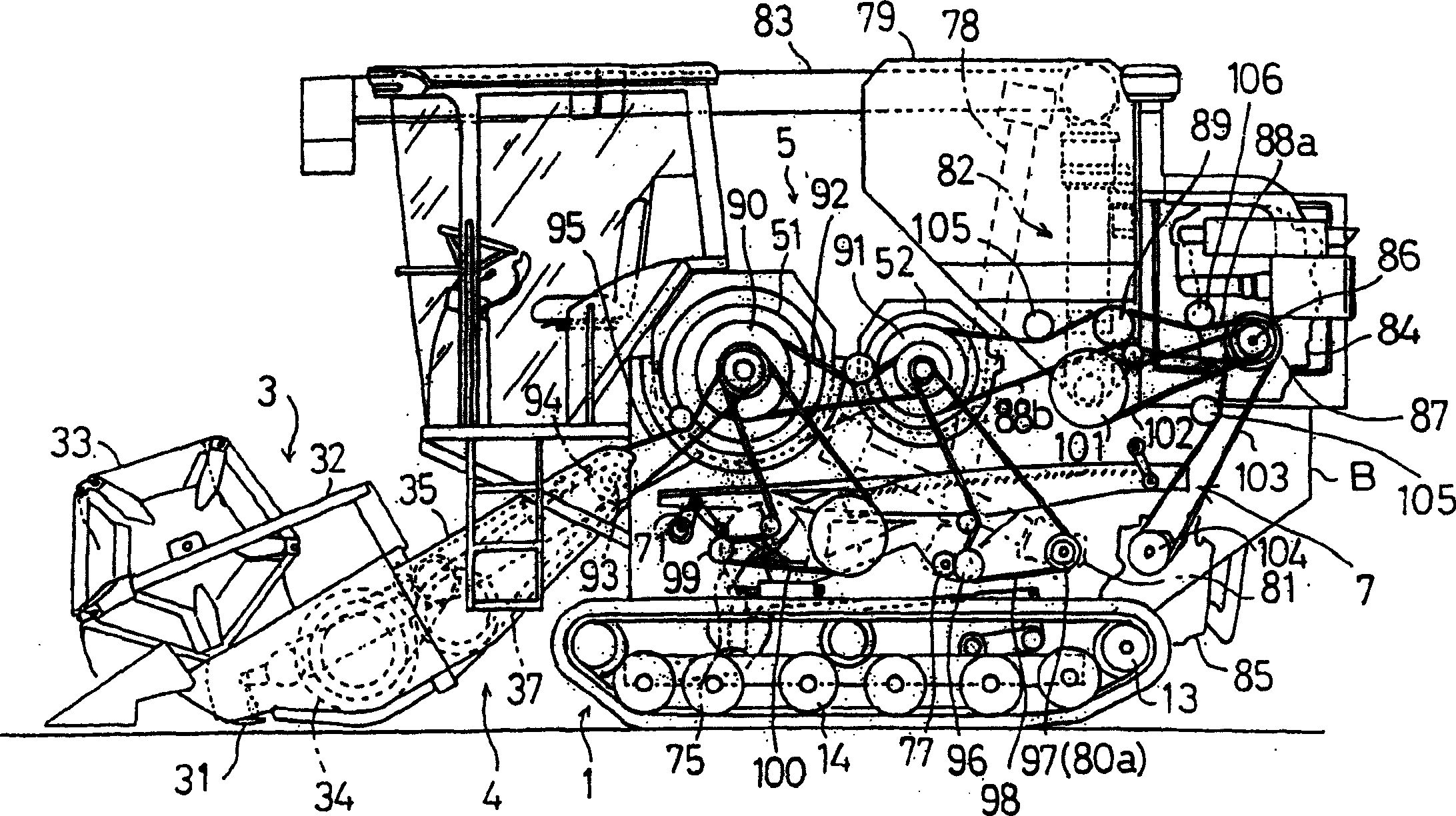
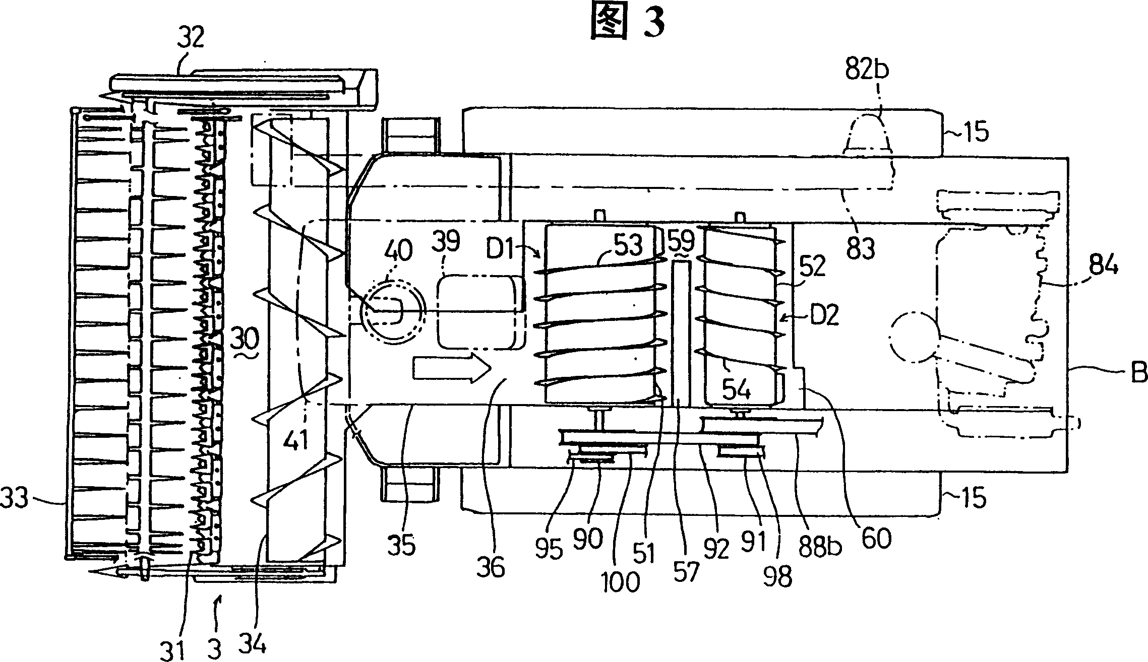
[0060] Figure 1 to Figure 11 The basic example of the general-purpose combine harvester A of this invention is shown. First, the general-purpose combine A of this basic implementation side is demonstrated. In addition, the left-right relationship is relative to the front-back direction of the body.

[0061] This general-purpose combine harvester A mounts the main machine B on the top of the running part 1, and the front of this main machine B protrudes and installs the reaping part 3 and the conveyance part 4 freely. As the transmission mechanism for the raising and lowering, for example, other examples will be described later. Figure 23 In , an embodiment is disclosed in which a lifting piston cylinder 140 of a hydraulic type or a pneumatic type is installed between the running part 1 and the feeder 35 .

[0062] walking part 1 such as figure 1 As shown, the driven wheel 12 and the driving force 13 are respectively supported on the front and rear ends of a pair of walki...


PUM


Abstract

A general purpose combined harvester and thresher comprising a first rotor (51) and a second rotor (52) provided in a thresh unit (5) and arranged longitudinally in parallel to each other with axes thereof right and left, and a first receiving net (55) and a second receiving net (56) arranged below the respective rotors to define a first treating chamber (D1) and second treating chamber (D2). A grain tank (79) is arranged above the threst unit (5), a base end of a discharge auger (83) is arranged outside the grain tank (79), an engine (84) is arranged behind the grain tank (79), and a transmission casing (85) is arranged below the engines A tooth bar (T1) is provided on an outer peripheral surface of the first rotor (51) facing a grain rod inlet (36), and a screw vane (53) has a pitch (P) equal to a width of a rear end of a feeder housing (35). A terminal end of a return conveyor (81) for returning of a second product communicates with the first treating chamber (D1).

Description

technical field [0001] The present invention relates to a structure of a general combine harvester in which a helical rotor is arranged at right angles to an advancing direction. Background technique [0002] Usually, the structure of general-purpose combine harvester is as follows, protrudingly set up harvesting part in the front of running device, the ear stalk harvested by this harvesting part is conveyed and supplied to the threshing part rearward, and this threshing part is arranged with the peripheral protruding part in front and rear direction. The helical rotor with helical blades is used for threshing by the rotation of the rotor, and the waste straw after threshing is discharged to the threshing ground behind the machine body, and the grains, grain husks, dust, etc. leaked from the screen are arranged in the The screening device under the threshing part screens, the grain shavings and dust are discharged from the rear of the machine, and the fine grains are stored ...

Claims


Application Information

Patent Timeline
IPC IPC(8): A01D41/02A01F12/00A01F12/20
CPCA01F12/20A01D41/02A01F12/00
Inventor 山本明人浜田健二中村正美桐畑俊纪寺岛淳正野润一新福勇一
Owner YANMAR CO LTD
Why Eureka
Try Eureka