Electric connector

A technology of electrical connectors and connecting parts, applied in the field of piercing electrical connectors, can solve the problems of reduced reliability of electrical connections, and achieve the effect of high reliability and high reliability

Inactive Publication Date: 2005-11-16
TYCO ELECTRONICS JAPAN GK
View PDF0 Cites 0 Cited by
  • Summary
  • Abstract
  • Description
  • Claims
  • Application Information

AI Technical Summary

Problems solved by technology

However, in the case of connection with a large number of core wires, for example 60 core wires, the core wires tend to move in the slots, so that the reliability of the electrical connection is reduced

Method used


Image

  • Electric connector
  • Electric connector
  • Electric connector

Examples


Embodiment Construction

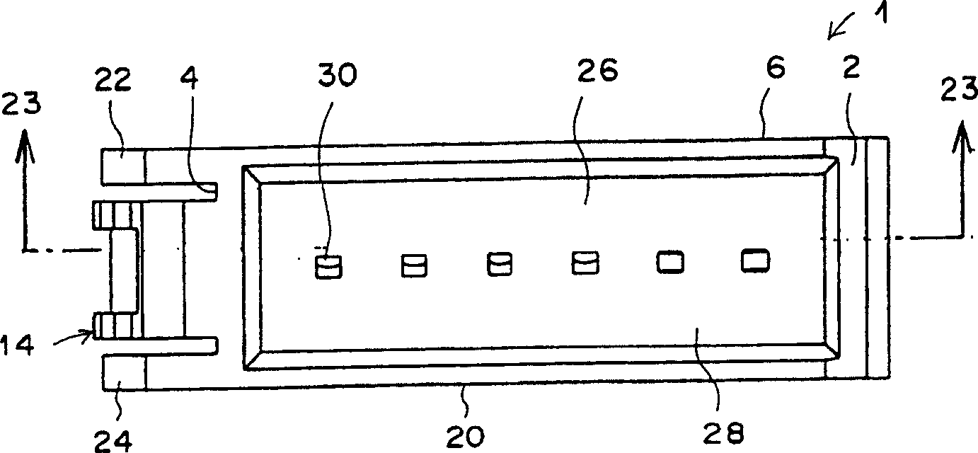
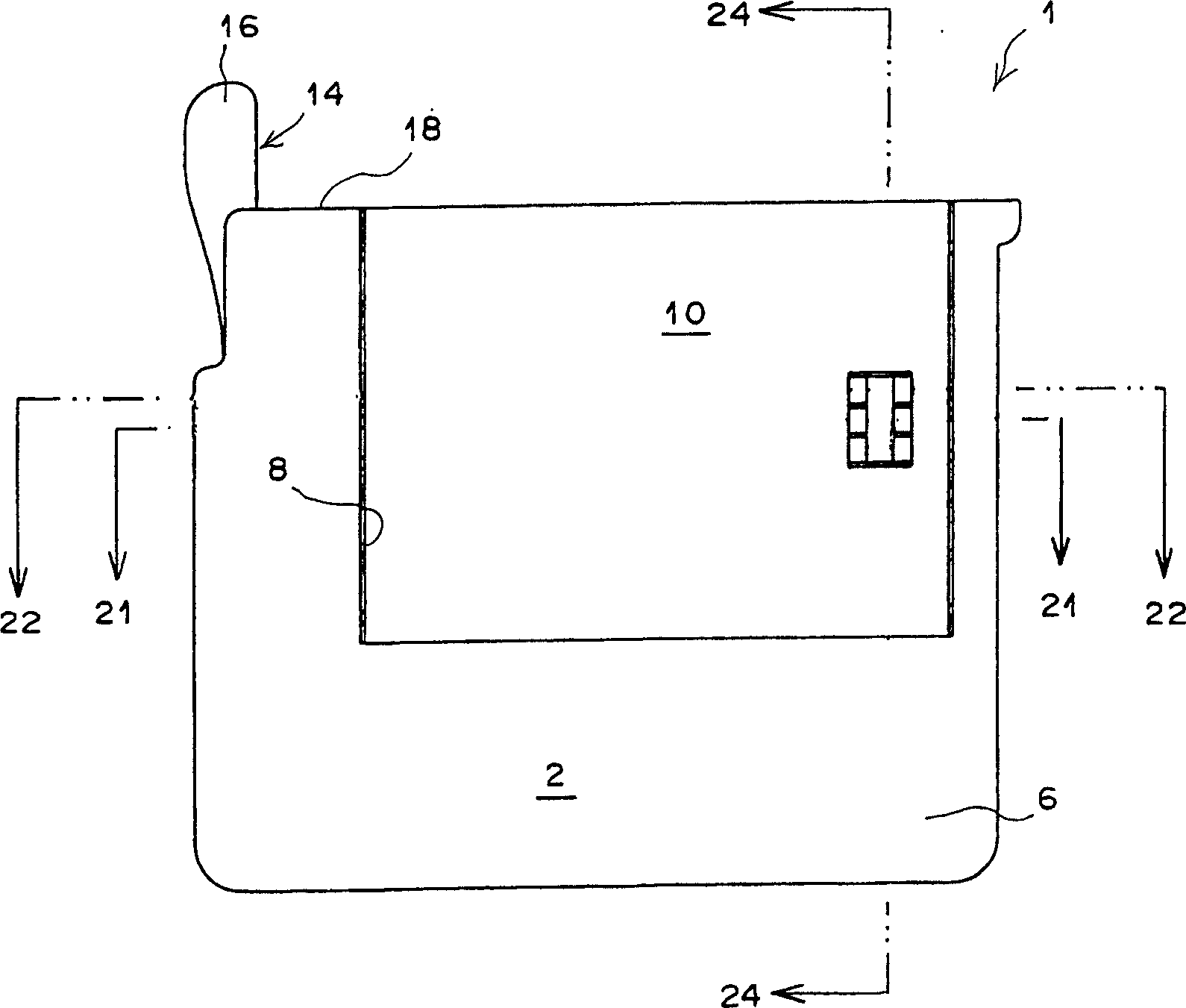
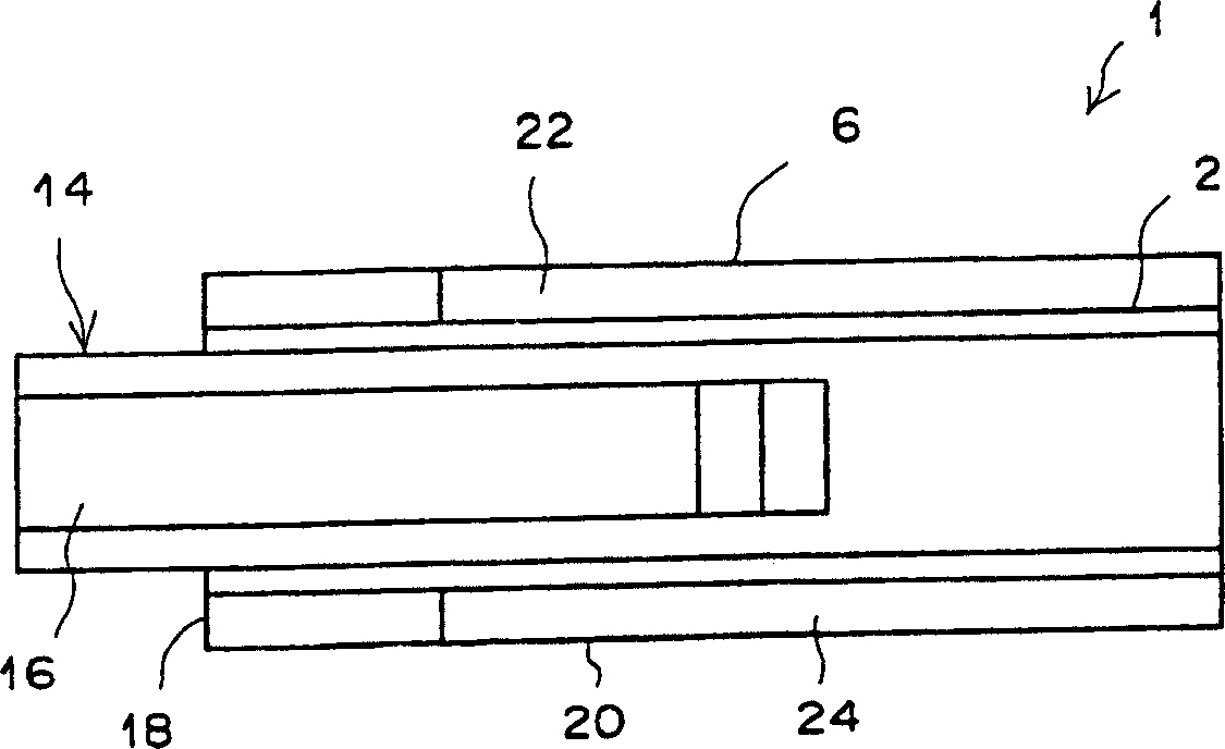
[0051] Preferred embodiments of the present invention will be described in detail below with reference to the accompanying drawings. figure 1 is a front view of the connector constituting the first embodiment of the present invention. figure 2 Yes figure 1 A floor plan of the connector shown. image 3 Yes figure 1 Left side view of the connector shown. Figure 4 is figure 1 Rear view of the connector shown. Refer below figure 1 Refer to Fig. 4 for description.

[0052] The housing 2 used in the connector 1 is substantially rectangular, and its plan view is close to a square. On the upper wall 6 of the housing 2, a rectangular groove 8 is formed, so that the groove 8 is separated from the housing 2 (in the figure 2 The bottom of the) near the center of the front part of the extension ( figure 2 ). The slot 8 is open towards the rear at the top. A cover housing 10 whose shape is complementary to the groove 8 is mounted inside the groove 8 . A circular hole 12 for d...


PUM


Abstract

A connector has a housing, contacts, and a cover housing which is mounted in the housing. Electrical wires are passed through the cover housing, and the tip end portions of the electrical wires are held by clips. When the cover housing holding the electrical wires is pushed into the recess of the housing, the protruding tongue parts of the contacts pierce the outer coverings of the electrical wires, and bite into the conductors of the electrical wires. Since the supporting arms of the clips are positioned so that these supporting arms correspond to the protruding tongue parts, the insulating outer coverings of the electrical wires that are electrically connected by the protruding tongue parts are elastically pressed toward the protruding tongue parts from the outside by the supporting arms of the clips.

Description

technical field [0001] The present invention relates to an electrical connector which is connected to electric wires having a large number of core wires (conductors) and is used in fields such as semiconductor manufacturing equipment, industrial machinery and automobiles; more specifically, the present invention relates to a A piercing type electrical connector, in which the electrical connection between the wire and the contact is achieved by piercing the wire by a part of the contact (ie, the connecting portion that forms a connection with the wire). Background technique [0002] In general, a connector disclosed in Japanese Unexamined Patent Publication 61(1986)-133584 has become a well-known electrical connector of this type (hereinafter simply referred to as "connector"). This connector is equipped with a bottom housing having a groove opened to the outside, contacts disposed in the groove, and a cover housing fitted in the groove. A plurality of slots are formed in th...

Claims


Application Information

Patent Timeline
IPC IPC(8): H01R4/24
CPCH01R13/506H01R4/2433H01R4/2404H01R4/242H01R4/24
Inventor 光木大辅
Owner TYCO ELECTRONICS JAPAN GK
Why Eureka
Try Eureka