
Fuel soft tube mounting structure of fuel jet engine

A technology for mounting structures and engines, which is applied to combustion engines, internal combustion piston engines, engine components, etc., can solve the problems of unconfigurable, limited engine space, and reduced reliability of connections, so as to improve reliability, reduce the number of pipelines, Effect of improved connection reliability

Inactive Publication Date: 2005-11-30
YAMAHA MOTOR CO LTD
View PDF1 Cites 0 Cited by
  • Summary
  • Abstract
  • Description
  • Claims
  • Application Information

AI Technical Summary

Problems solved by technology

Therefore, the reliability of the connection will be reduced
[0011] In addition, compared with four-wheeled vehicles, small motorcycles equipped with swing component engines have limited space around the engine, so there are many restrictions on the layout of the fuel pipeline. In addition, because the engine itself will swing relative to the body (in small 8-10cm relative to the body of a scooter), so it cannot be configured according to the fuel pipeline structure of a conventional four-wheeled vehicle

Method used


Image

  • Fuel soft tube mounting structure of fuel jet engine
  • Fuel soft tube mounting structure of fuel jet engine
  • Fuel soft tube mounting structure of fuel jet engine

Examples


Embodiment Construction

[0047] Embodiments of the present invention will be described below with reference to the drawings.

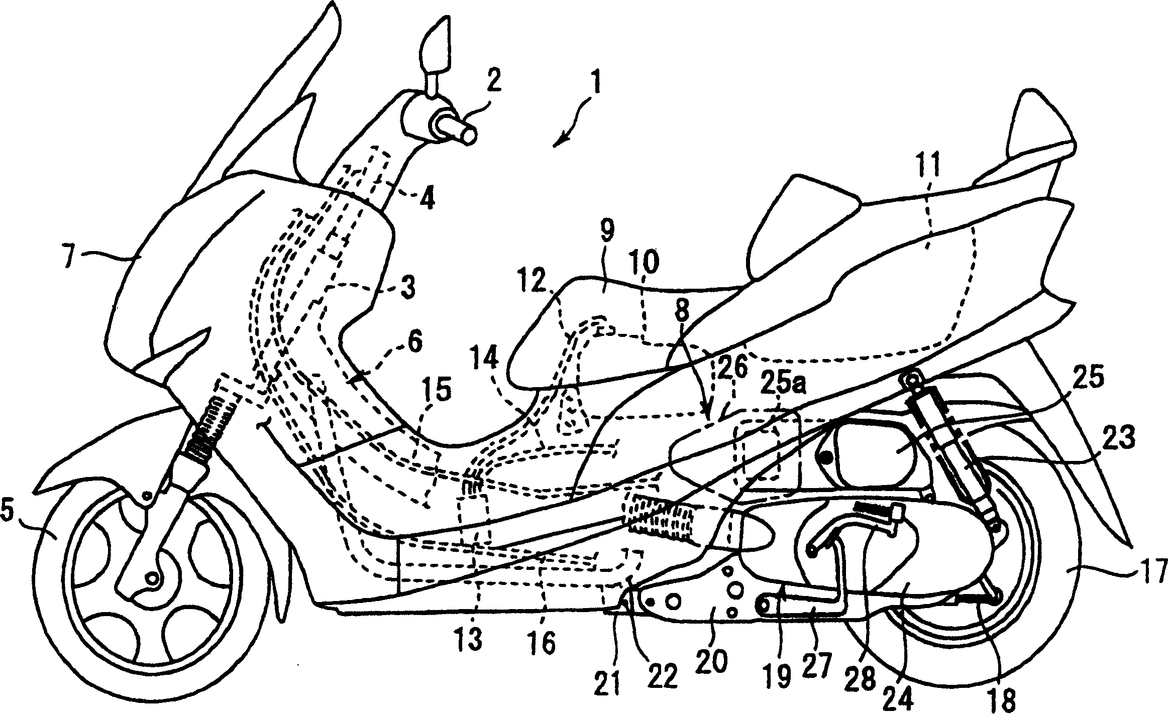
[0048] figure 1 It is an external view of a scooter suitable for the present invention.

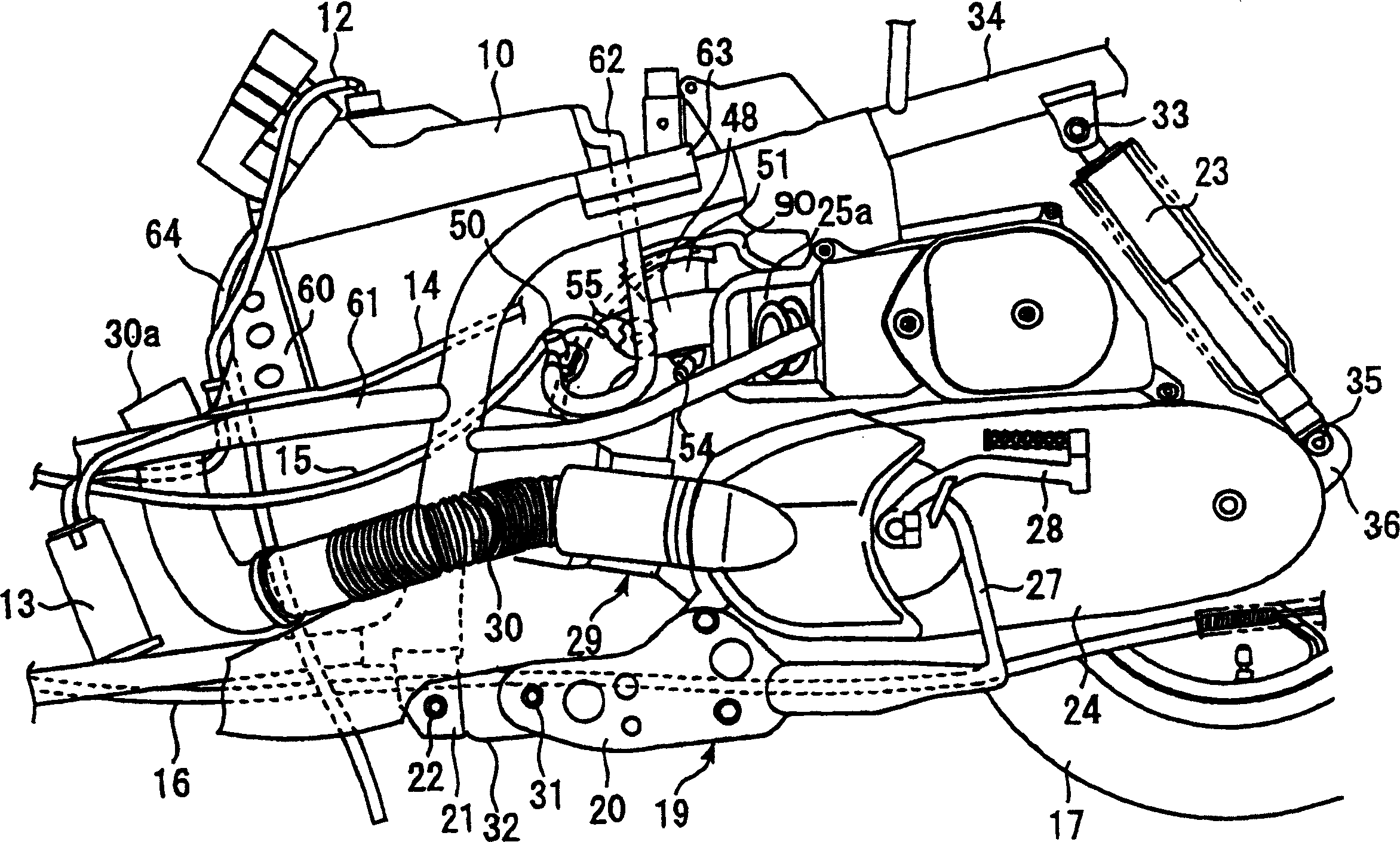
[0049] The front part of the car body 1 has a handlebar 2, and the handlebar 2 is connected with the front wheel 5 through the steering shaft 4 inserted with the front pipe 3. The vehicle body frame 6 is combined with the head pipe 3 . The vehicle body frame 6 forms the overall frame structure of the vehicle. The front portion of the vehicle body is covered with a cowl 7 . From the outside of the vehicle body frame 6 , the vehicle body 1 is covered by a vehicle body cover 8 . Car body center is provided with vehicle seat 9, and its underside is provided with fuel tank 10, and its rear is provided with hood box (loading) 11. The fuel tank 10 supplies fuel to a nozzle (not shown) through a fuel hose (not shown). One end of a breather hose 12 is connected to the upper portion of the fu...


PUM


Abstract

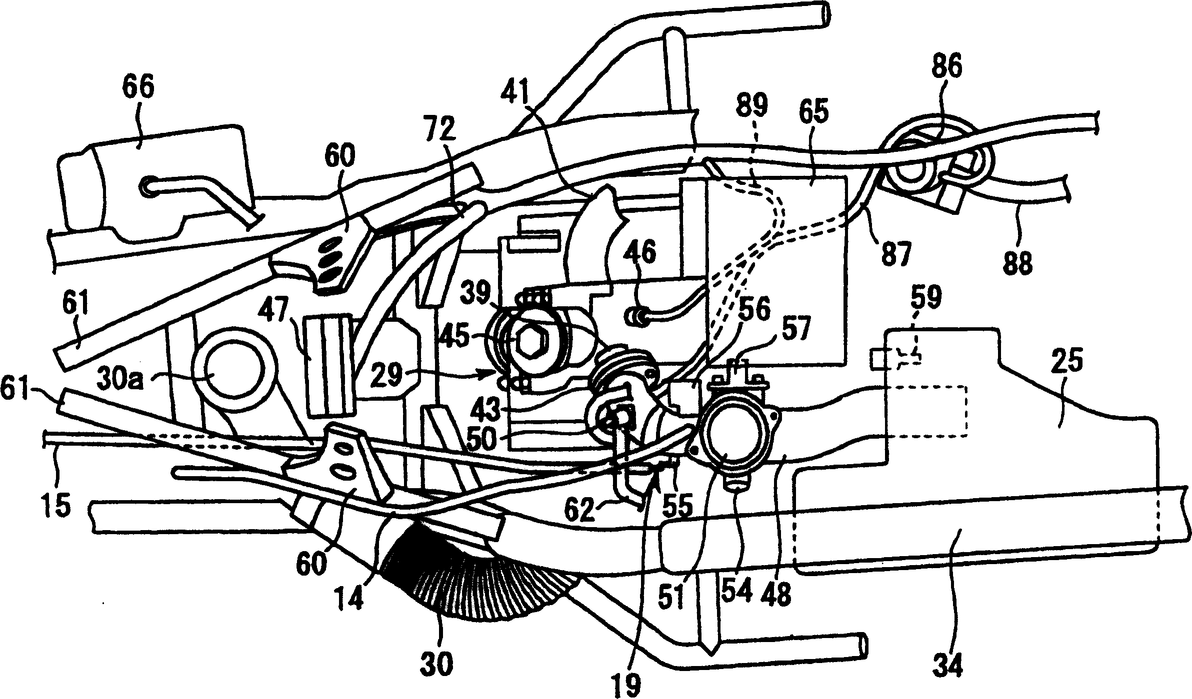
The object of the present invention is to provide a fuel hose mounting structure which improves reliability of the connecting part of the fuel hose in a swing unit type fuel injection engine. The solution of the present invention is a fuel hose mounting structure for motorcycle which comprises a fuel injection engine having an injector is formed integrally with a decelerator coupled to a rear wheel to constitute an engine unit. The engine unit is pivotally mounted to a body frame (34). The engine unit and the rear wheels are pivotally attached to the body. A fuel tank (10) is arranged on the body frame (34). The fuel tank (10) and the injector are connected by a fuel hose (62). The present invention is characterized in that while a middle part of the fuel hose 62 is fixed to the body frame (34), the fuel hose (62) arranged between a fixing part (for example, a stay 63) to the body frame (34) of the fuel hose (62) and the injector is configured to be elastically deformed according to the swing motion of the engine unit.

Description

technical field [0001] The invention relates to a fuel hose installation structure of a swing assembly type fuel injection engine. Background technique [0002] Oscillating unit engines are used in small motorcycles such as scooters. The crankcase and reduction box of the swing component engine are integrally combined to form an engine assembly. The reducer is connected to the rear wheel and is installed on the vehicle body frame through a shock absorber and can swing. The front part of the engine assembly is fixed on the vehicle body frame through a shaft. superior. Therefore, the engine assembly can rotate together with the rear wheel within a certain angle range centered on the shaft, absorbing the swing generated by the vehicle body frame during travel. [0003] Such a swing unit type engine is described in Patent Document 1, for example. [0004] As the oscillating assembly engine of such a small motorcycle, a 2-stroke engine or a 4-stroke engine with a carburetor or...

Claims


Application Information

Patent Timeline
Patent Type & Authority Patents(China)
IPC IPC(8): F02M37/00B62M7/02F02M37/10
CPCY02T10/123Y02T10/12
Inventor 片冈政士竹内昭光杉谷刚
Owner YAMAHA MOTOR CO LTD
Learn More