Runway type pneumatic drilling machine

A pneumatic drilling rig, runway-type technology, which is applied to rotary drilling rigs, impact drilling, rotary drilling and other directions, can solve the problems of inability to fully control the drilling rig, difficulty in constructing discharge holes, and the need for many personnel. Improve the ability to fight against unexpected risks, ensure safety and stability, and reduce labor intensity

Inactive Publication Date: 2016-12-07
BAICHENG ZHONGWEI COAL IND CO LTD
View PDF14 Cites 0 Cited by
  • Summary
  • Abstract
  • Description
  • Claims
  • Application Information

AI Technical Summary

Problems solved by technology

Restricted by terrain conditions, the drilling angle for construction release is mostly -30° or +30°. During the construction of the discharge hole, it is difficult, requires many personnel, and insufficient propulsion force
Moreover, once the problem of drill sticking is encountered, even if multiple people hold the drill together, they cannot fully control the drill
Therefore, when the drill is stuck, it will cause the drilling machine to collapse and injure the personnel.

Method used


Image

  • Runway type pneumatic drilling machine
  • Runway type pneumatic drilling machine

Examples


Embodiment 1

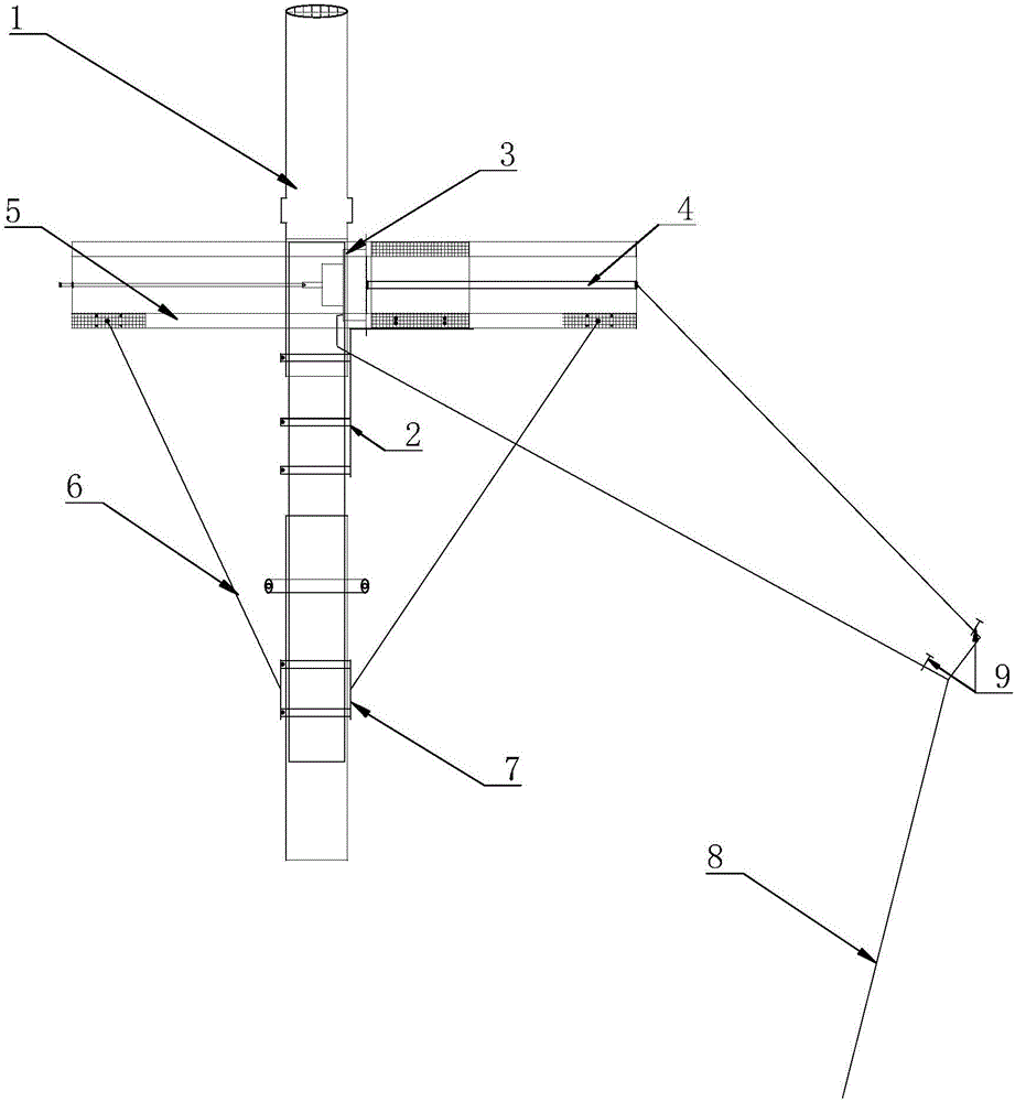
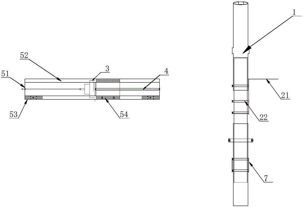
[0025] figure 1 It is a structural diagram of Embodiment 1 of the present invention, figure 2 is the invention figure 1 A partial disassembly schematic.

[0026] In the figure, the meanings of each reference sign are as follows: 1. Single hydraulic prop; 2. Second fixing device; 21. Arc plate; 22. Second fixing plate; 3. Pneumatic drilling machine; 4. Air pressure type Propelling cylinder; 5. Rig runway; 51. End baffle; 52. Guide column; 53. Support rod fixing device; 54. First fixing plate; 6. Support rod; 7. Third fixing device; 8. Main pipe ; 9. Ball globe valve.

[0027] In the figure, the meanings of each reference sign are as follows: 1. Single hydraulic prop 1; 2. Second fixing device 2; 21. Arc piece 21; 22. Second fixing plate 22; 3. Pneumatic drilling machine 3; 4. Air pressure propulsion cylinder 4; 5. Rig runway 5; 51. End baffle 51; 52. Guide column 52; 53. Support rod 6 fixing device 53; 54. First fixed plate 54; 6. Support rod 6; 7. The third fixing device...


PUM


Abstract

The invention relates to a runway type pneumatic drilling machine. The runway type pneumatic drilling machine comprises a pneumatic drilling machine body. The pneumatic drilling machine body and a drilling machine runway are connected in a circumferentially fixed and axially sliding mode. The pneumatic drilling machine body is further connected with a pushing cylinder mounted on the drilling machine runway. The drilling machine runway is mounted on a strut. Through the runway type pneumatic drilling machine, the production accidents that rotation of the drilling machine threatens the personal safety can be avoided.

Description

technical field [0001] The invention belongs to the technical field of coal mining, in particular to a track-type pneumatic drilling machine. Background technique [0002] For high-gas mines, the coal seam to be mined has outstanding hazards, and local discharge boreholes need to be constructed during roadway excavation. Pneumatic hand-held drilling rigs are used during partial discharge drilling, and mine pressure air is used as the power source for the drilling rig. Restricted by terrain conditions, the drilling angle for construction release is mostly -30° or +30°. During the construction of the discharge hole, it is difficult and requires many personnel and insufficient propulsion. Moreover, once the problem of drill sticking is encountered, even if multiple people hold the drill together, they cannot fully control the drill. Therefore, when the drill is stuck, the drilling rig will collapse and the personnel will be injured. Contents of the invention [0003] In or...

Claims


Application Information

Patent Timeline
Patent Type & Authority Applications(China)
IPC IPC(8): E21B3/02E21B15/00
CPCE21B3/02E21B15/003
Inventor 焦太显赵忠贤单成方王风鸣刘洋毛宗民李红伟李国强李亚锋万威
Owner BAICHENG ZHONGWEI COAL IND CO LTD
Why Eureka
Try Eureka