
Methods and apparatus for reducing viberations induced within fan assemblies

A technology for fan components and equipment, applied in mechanical equipment, pump components, machines/engines, etc., can solve problems such as expensive, complex, and damping system failures

Inactive Publication Date: 2006-02-15
GENERAL ELECTRIC CO
View PDF0 Cites 1 Cited by
  • Summary
  • Abstract
  • Description
  • Claims
  • Application Information

AI Technical Summary

Problems solved by technology

Such systems are quite complex and expensive, and over time, continuous exposure to vibration may cause the damping system to fail, such that the vibrational energy may loosen the fan assembly from the component, potentially causing the fan assembly or component to fail

Method used


Image

  • Methods and apparatus for reducing viberations induced within fan assemblies
  • Methods and apparatus for reducing viberations induced within fan assemblies
  • Methods and apparatus for reducing viberations induced within fan assemblies

Examples


Embodiment Construction

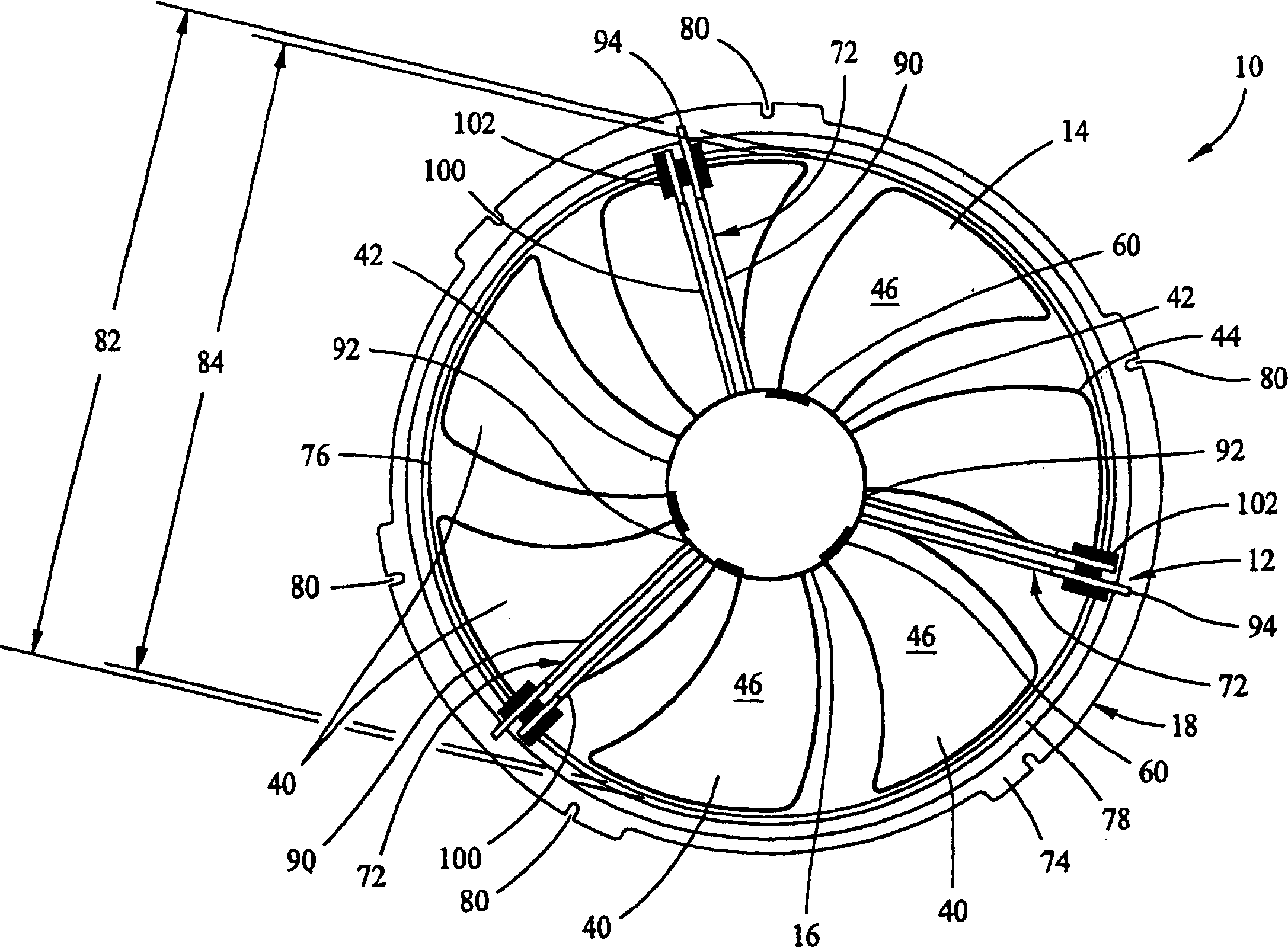
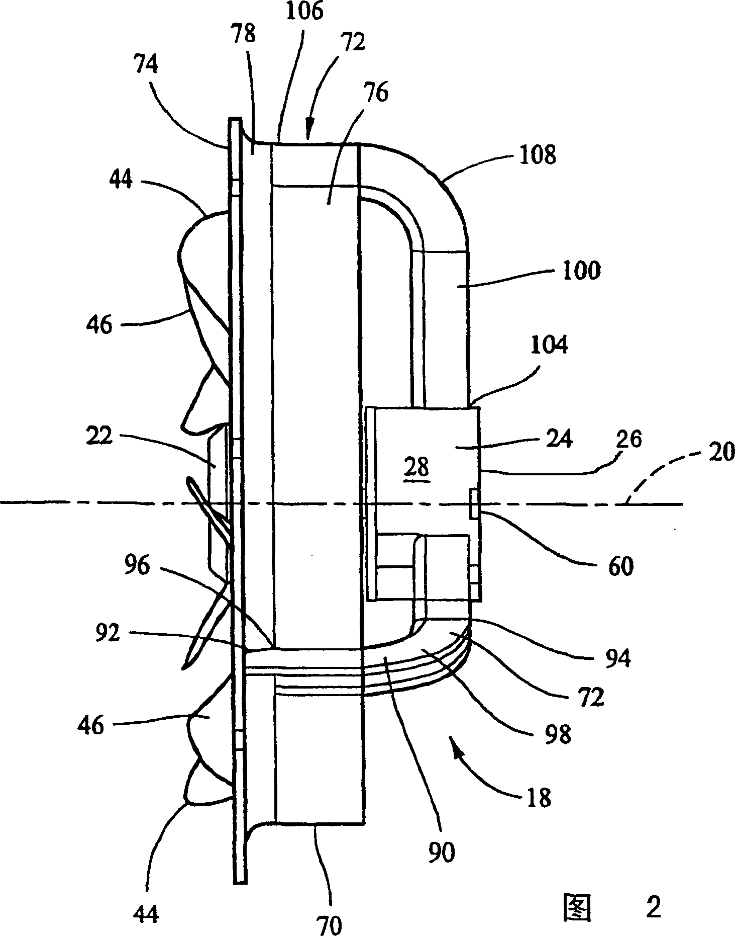
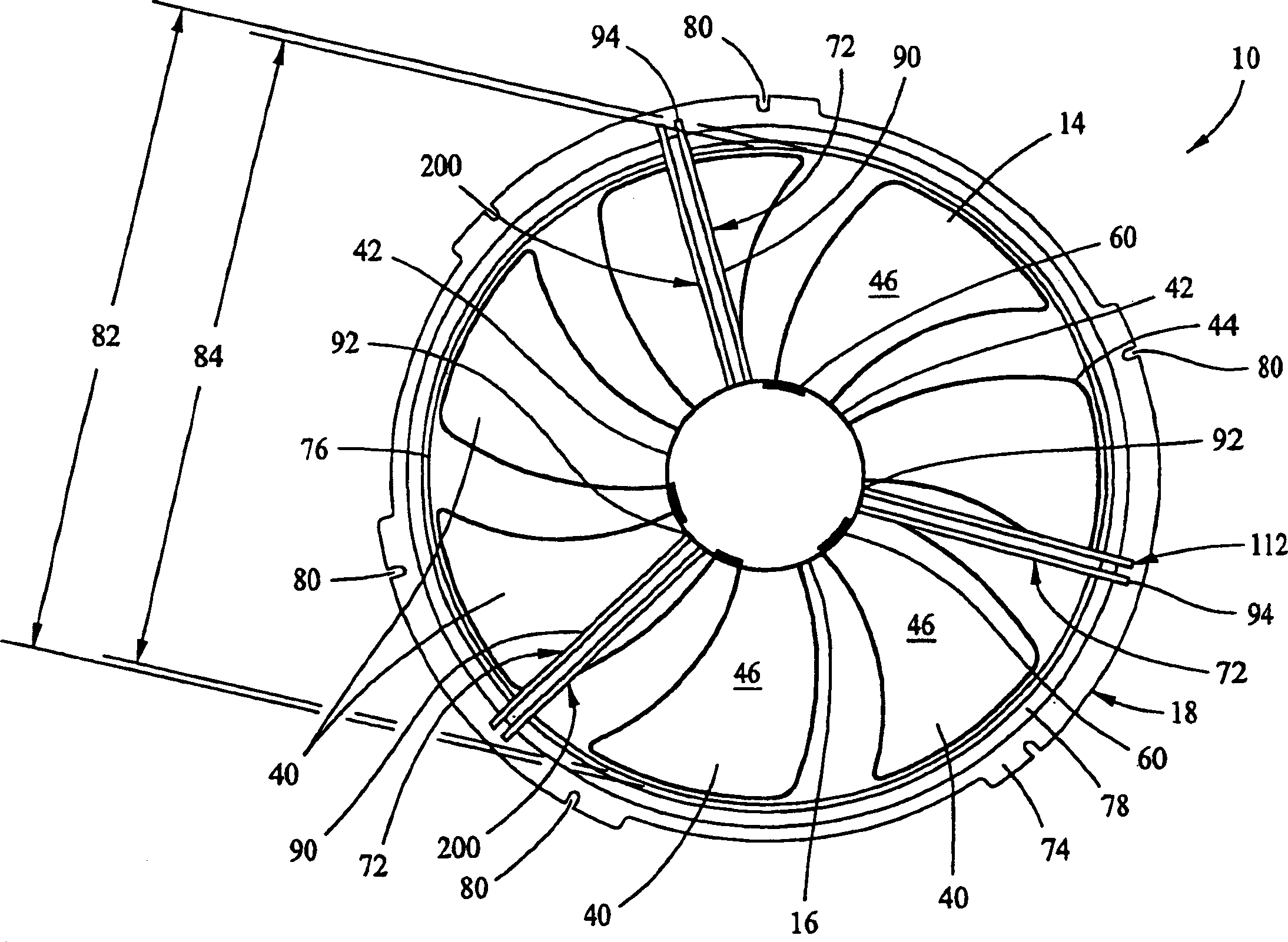
[0014] figure 1 and 2 are rear and side views, respectively, of the fan assembly 10 including the vibration damping system 12 . Fan assembly 10 includes a motor (not shown), a control unit (not shown), a fan 14 , a motor housing 16 , and a shield assembly 18 . The motor and fan control device is disposed inside the motor housing 16 and controls power to the fan 14 and controls rotation of the fan 14 about the axis of rotation 20 .

[0015] The motor housing 16 includes a rotating portion 22 and a stationary or shielding cup portion 24 . Stationary portion 24 is generally cylindrical and includes top 26, side walls 28, and a bottom flange (not shown). Side walls 28 extend substantially vertically from top 26 to the bottom flange. The bottom flange extends radially outwardly from the side wall 28 and enables the stationary portion 24 to be in sealing and rotatable contact with the rotating portion 22 .

[0016] The fan 14 is mounted to the rotating portion 22 and includes a ...


PUM


Abstract

A fan assembly includes a vibration damping system (12) to reduce induced vibrational energy generated as a result of fan motor (26) operation. The vibration damping system (12) includes a plurality of arms (100) and damping material (102). The vibration damping system arms extend between a fan motor and a shroud assembly disposed circumferentially outward from the fan motor housing. The damping material (102) is attached to an end of each of the vibration damping system arms (100) and connects each arm to the shroud assembly. The damping material (102) absorbs induced vibrational energy generated by fan motor operation.

Description

technical field [0001] The present invention relates generally to fan assemblies and, more particularly, to vibration dampening systems for use with fan assemblies and methods of reducing vibration induced in fan assemblies. Background technique [0002] Fan assemblies typically include a fan, a motor, a fan control, and a motor housing. The fan motor and the control device are arranged in the motor casing, and control the supply of power to the fan and the rotation of the fan. Because fan assemblies are often used in applications requiring high air flow, the fans typically operate at very high speeds in order to provide sufficient air flow to the components. Fan imbalances and motor torque pulses produced by such fan assemblies can cause vibrations that can generate unwanted noise when such fan assemblies are mounted by the mounting system in the application. [0003] Motors producing such operating speeds can cause potentially damaging vibrations to the fan assembly, whi...

Claims


Application Information

Patent Timeline
IPC IPC(8): F04D29/66F04D25/08F04D29/60
CPCF04D25/08F04D29/668F04D29/601
Inventor R·K·霍伦贝克J·E·格里姆D·L·史密斯K·B·舍尔顿
Owner GENERAL ELECTRIC CO
Learn More