
Cooling device in a projector

A projector and air flow technology, which is used in projection devices, instruments, optics, etc., can solve the problems of damaged fan service life and inability to withstand high temperature.

Inactive Publication Date: 2006-03-29
SEIKO EPSON CORP
View PDF0 Cites 0 Cited by
  • Summary
  • Abstract
  • Description
  • Claims
  • Application Information

AI Technical Summary

Problems solved by technology

The difficulty is that when these components are made as small as possible, small fans must also be used, and these small fans are, in essence, not structurally capable of withstanding high temperatures
So when a fan removes heat by drawing air away from an overheated component, such as a light source, the fan itself will heat up, its bearings will dry out (the oil that lubricates the bearings dries out), and the fan will run briefly will be destroyed after the useful life of the

Method used


Image

  • Cooling device in a projector
  • Cooling device in a projector
  • Cooling device in a projector

Examples


Embodiment Construction

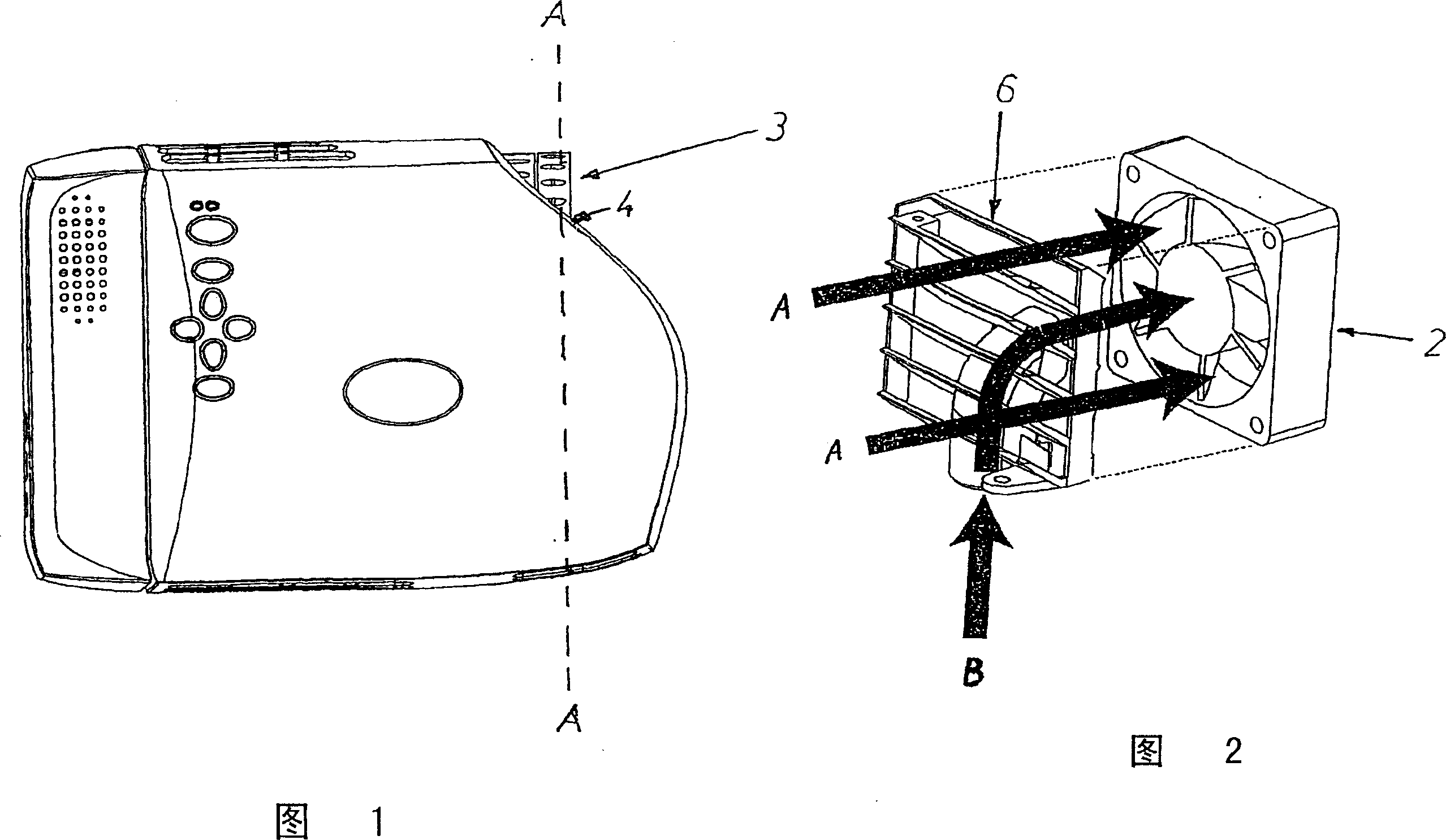
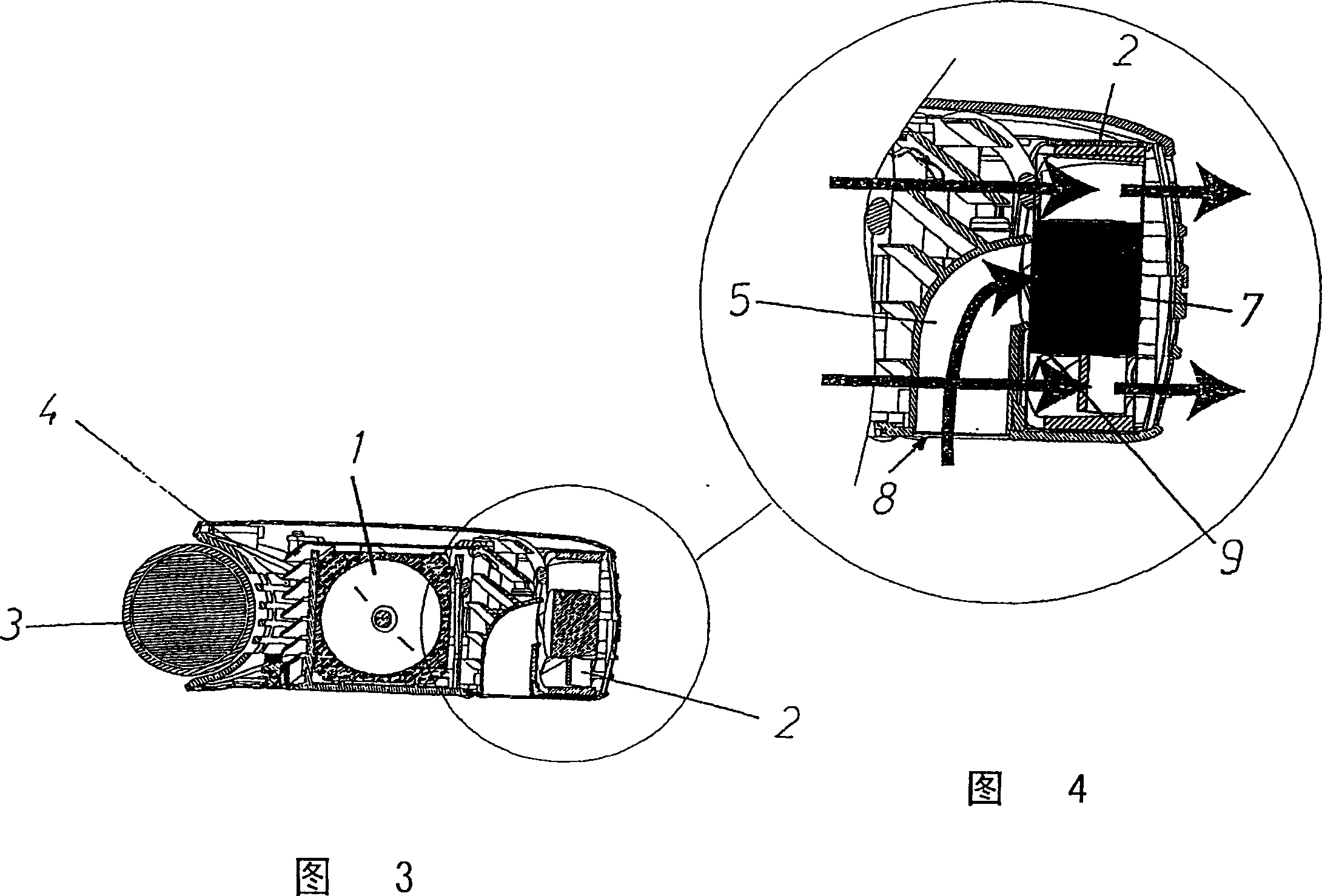
[0021] FIG. 3 shows the light source 1 and the exhaust fan 2 , which sucks air from the side of the light source 1 and its surroundings. This part of the projector, containing the device according to the invention, extends slightly beyond the lens 3 so that the air inlet 4 of this part is located in front, on the same side as the lens 3; see FIG. 1 . In order to make the fan motor withstand the high temperature of the air sucked in through the air inlet 4, the air can also be sucked in from the bottom of the projector through the inlet 8 of the ventilation duct 5. In front of the fan 2 there is a louver 6; see Fig. 4 and Fig. 2 . In addition, the louver 6 also has the function of preventing light from being scattered to the surroundings by the fan. In addition, the slats of the louvers are positioned obliquely so that the vertical velocity of the airflow obliquely directed towards the fan corresponds to the vertical velocity of the airflow from the inlet 8, but in the opposit...


PUM


Abstract

A device for cooling a light source (1) in a compact projector in a noiseless manner with the aid of a suction fan (2), where in front of the suction fan there is provided a duct (5) having an intake (8) for direct suction of surrounding air or cooled air. The duct (5) with the intake for cooling air is integrated in a louver (6) for flow therethrough of the air, heated by the light source (1), that is to be removed. The duct (5) is curved on one side thereof and in addition has a uniform cross section across its entire length so that the air shall have the same velocity over the entire duct and, at the same time, shall not create turbulence. The relationship between the curvature of the duct (5) and the slanted positioning of the slats of the louver (6) is such that the vertical components of the air stream in the duct (5) and the air stream over and around the light source (1) cancel each other out by virtue of the suction of the fan (2).

Description

technical field [0001] The invention relates to a device for cooling a projector comprising a light source, a suction fan with a built-in motor, a plurality of air intake holes and a louver, wherein the light source is located between any of the air intake holes and the suction fan In time, the light source can scatter heat into the air flow passing it. Background technique [0002] The current trend is that the market generally desires products that are small, compact and light in weight. This also applies to video projectors. However along with the miniaturization of products such as video projectors it is also desirable that they produce as little noise as possible; ideally be able to operate completely silently. [0003] Theoretically, it is possible to make a video projector operate noiselessly when the video projector consists only of optical and electrical components. The reality is somewhat different, because one of the main elements of the projector is a strong l...

Claims


Application Information

Patent Timeline
Patent Type & Authority Patents(China)
IPC IPC(8): G03B21/16
CPCG03B21/16
Inventor M·古利克森
Owner SEIKO EPSON CORP
Learn More