
Circular screen printer with humidification device

A humidification device and printing machine technology, which is applied to screen printing machines, printing machines, rotary printing machines, etc., can solve the problems of unstable printing and dyeing quality, volatile moisture, and large volume of humidification devices, so as to avoid hard strips and dyeing. The effect of unevenness, solving the problem of tops touch-up, and improving the quality of printing and dyeing

Inactive Publication Date: 2016-05-18
SUZHOU RUIRI TEXTILE SCI & TECH
View PDF7 Cites 0 Cited by
  • Summary
  • Abstract
  • Description
  • Claims
  • Application Information

AI Technical Summary

Problems solved by technology

During the working process of the rotary screen printing machine, it is necessary to maintain a certain humidity in the printing and dyeing workshop, because after the water-based ink used in printing is in contact with dry air for a long time, the water is easy to volatilize and increase the viscosity, resulting in unstable printing and dyeing quality. Dirty version, paste version, etc.
However, large-scale humidification in the printing and dyeing workshop has the disadvantages of high energy consumption and difficulty, and will increase production costs, and the printing and dyeing equipment has extremely high requirements on the humidity of the working environment, which will bring a lot of inconvenience to printing and dyeing and operation. In addition, most of the existing humidifiers have large and heavy water storage containers, and need to continuously add water to the water storage container. Regardless of whether the water storage container is installed inside or outside the humidifier, the operation is cumbersome and difficult to use. there will be a lot of inconvenience

Method used


Image

  • Circular screen printer with humidification device
  • Circular screen printer with humidification device
  • Circular screen printer with humidification device

Examples


Embodiment Construction

[0020] In order to make the technical means, creative features, objectives and effects of the present invention easy to understand, the present invention will be further described below in conjunction with specific embodiments.

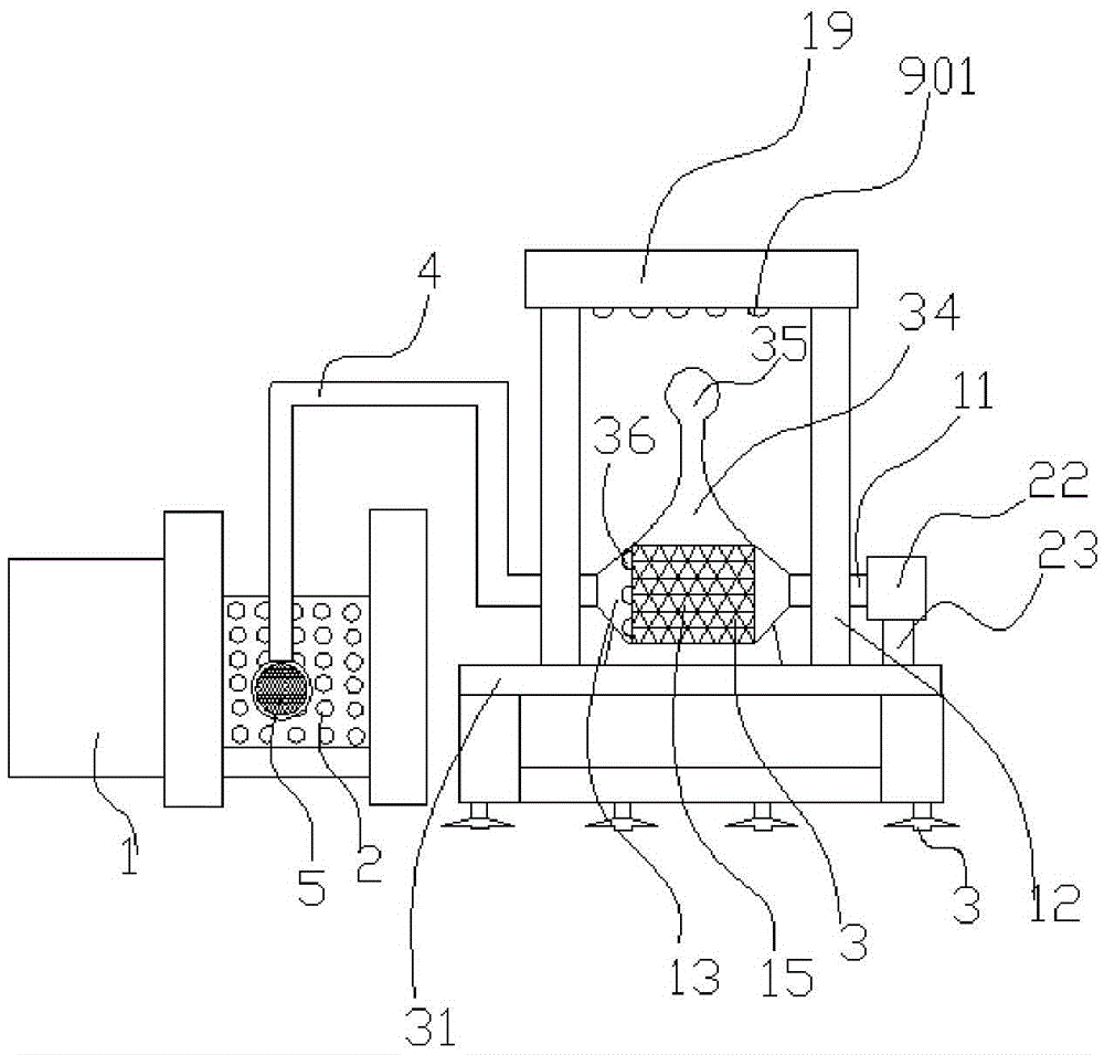
[0021] Such as figure 1 As shown, a rotary screen printing machine with humidification function includes a printing machine body 1, a screen plate 2 arranged on the printing machine body 1, a fixing frame 31 and a humidifying cylinder 3, and the nozzle 5 of the spray pipe 4 is aligned with the screen The board 2, the upper surface of the fixed frame 31 is fixed with a humidification pipeline support frame 12; the humidifier 3 is fixed above the fixed frame 31, and the outer surface of the humidifying cylinder 3 is uniformly provided with a plurality of humidification suction holes 15, and the two ends of the humidifier 3 are provided with There is a roller 13, one end of the humidifying cylinder 3 is provided with a nozzle 4, the other end is provided...


PUM


Abstract

The invention discloses a circular screen printer with a humidification device. The circular screen printer with the humidification device comprises a printer body, a screen plate, a fixing frame and a humidification drum, wherein the screen plate is arranged on the printer body; one end of the humidification drum is connected with a spray pipe; a spray nozzle of the spray pipe aligns to the screen plate; through holes are densely formed in the exterior of the screen plate; humidification pipeline supports are fixed to the upper surface of the fixing frame; the humidification drum is fixedly arranged on the fixing frame; multiple humidification air suction holes are uniformly formed in the outer surface of the humidification drum; rolling wheels are disposed at the two ends of the humidification drum; the spray pipe is disposed at one end of the humidification drum and a rotary shaft is mounted at the other end of the humidification drum; the rotary shaft is driven to rotate through a motor; two rows of steam humidification pipelines are disposed above the humidification drum; multiple humidification air outlet holes are uniformly formed in the outer surfaces, directly facing the humidification drum, of the steam humidification pipelines; and the humidification drum is a plastic drum.

Description

Technical field: [0001] The invention relates to the technical field of textile machinery, in particular to a rotary screen printing machine with a humidifying device. Background technique: [0002] The rotary screen printing machine used in textile mills is a screen printing machine that uses a continuously rotating seamless cylindrical screen for printing. The rotary screen printing machine is used in combination with other units. It can be used for printing cotton fabrics, chemical fibers and their blended fabrics, general knitted fabrics, and silk fabrics. The applicable raw materials are: nylon multifilament (thread), polypropylene filament ( yarn), polypropylene, polyester, nylon, PP, low elastic, high elastic, cotton yarn (thread), pearl yarn, leather, mixed, etc. The rotary screen printing machine has reasonable structure, easy operation and high production efficiency, so it is widely used in the field of textile production. During the working process of the rotary...

Claims


Application Information

Patent Timeline
Patent Type & Authority Applications(China)
IPC IPC(8): B41F15/08B41F15/14B41F15/40B41F23/02
CPCB41F23/02B41F15/08B41F15/14B41F15/405
Inventor 钱彩华
Owner SUZHOU RUIRI TEXTILE SCI & TECH
Learn More