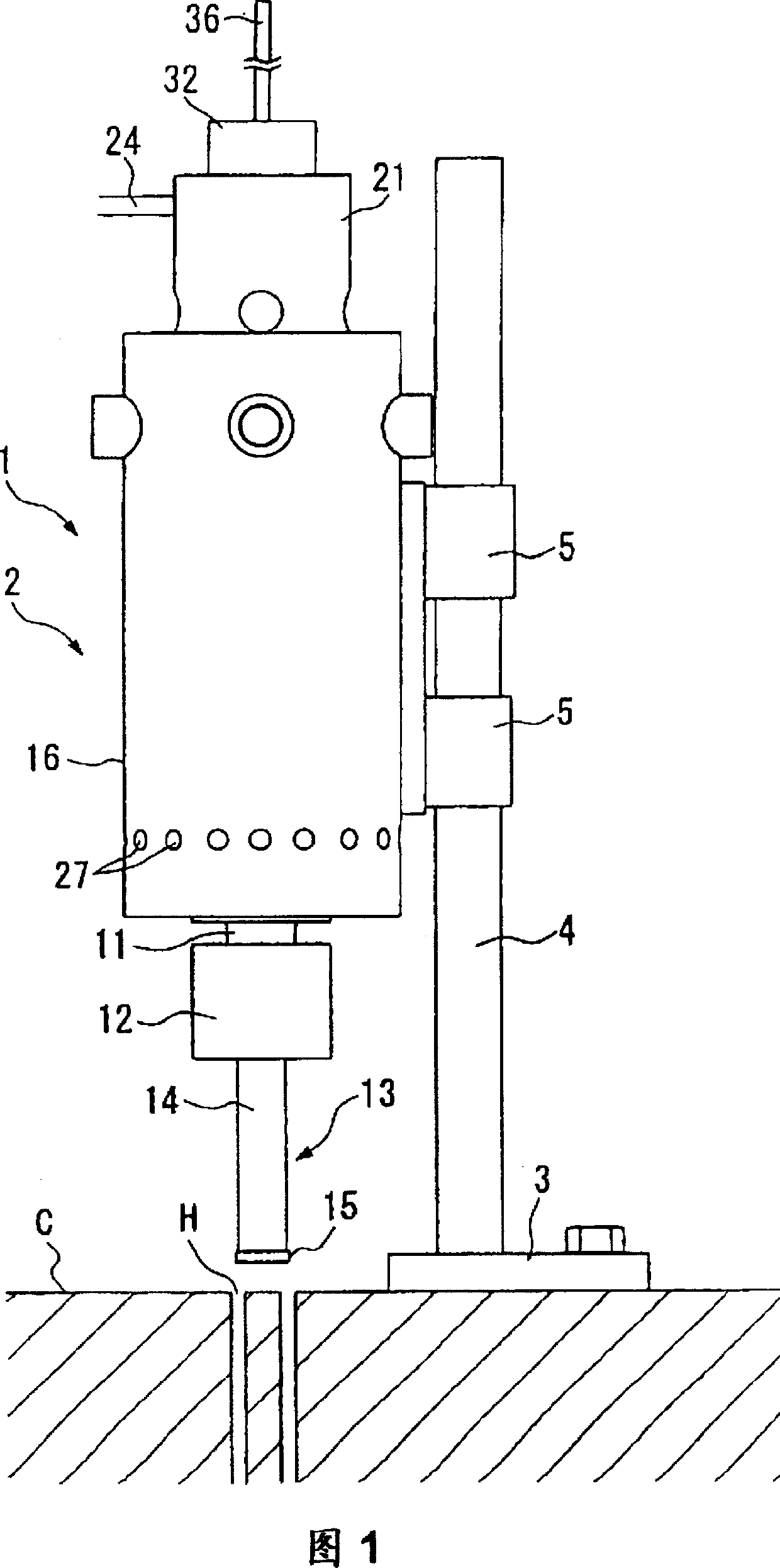
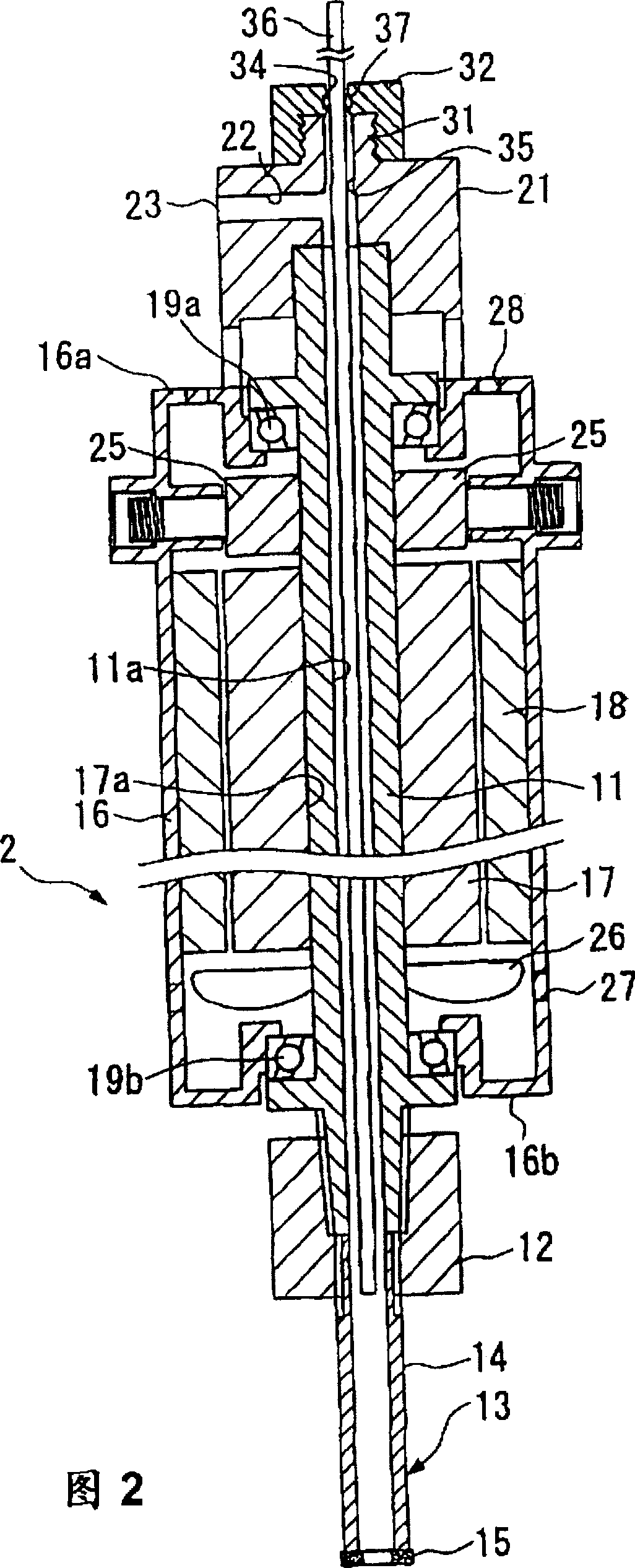
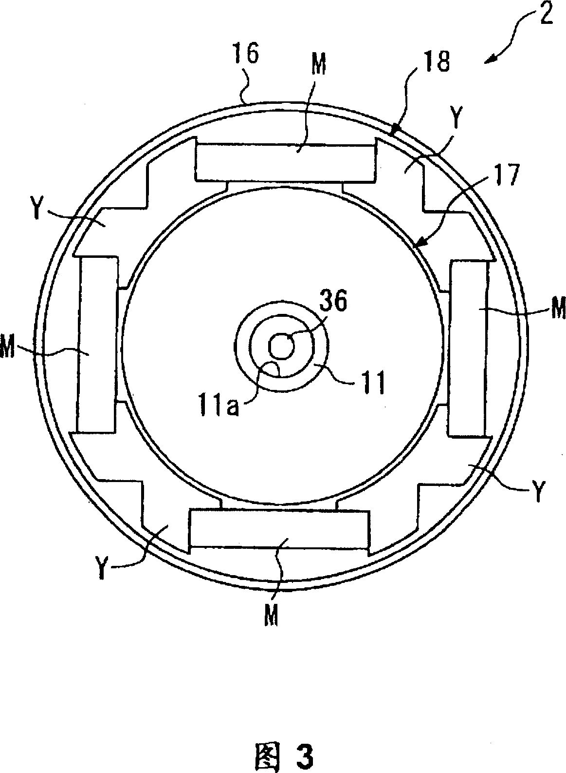
High speed boring apparatus.
A punching device, high-speed technology, applied in the direction of manufacturing tools, ship construction details, mechanical equipment, etc., can solve the problems of difficult operation, low punching speed, long time punching, etc., to increase the punching speed, reduce the Less labor, less noise effect
Inactive Publication Date: 2006-04-12
NIPPON DIAMOND CORP
View PDF1 Cites 0 Cited by
- Summary
- Abstract
- Description
- Claims
- Application Information
AI Technical Summary
Problems solved by technology
[0007] In the above device, as an engine oil hydraulic motor, the motor 81 is heavy and difficult to handle because the motor 81 includes a gear device through which the core drill 80 is driven to rotate.
In addition, the device has the problem of producing a lot of noise (greater than 90dB)
In addition, this device has the problem that the rotational speed is as low as about 1500 rpm (rotation per minute) even at high speed, and even if it is a special motor, its rotational speed can only reach the level of 3000-3900 rpm, so it takes a long time to print hole
[0008] The punching device that uses ultrasonic
Method used
View moreImage
Smart ImageViewing Examples
Examples
 PUM
| Property | Measurement | Unit |
|---|---|---|
| Outer diameter | aaaaa | aaaaa |
| Thickness | aaaaa | aaaaa |
Abstract
Disclosed is a high speed-perforating apparatus 1 comprising a rotor 17 into and through which a cylindrical rotary shaft 11 is integrally inserted, a stator 18 disposed around the outer periphery of the rotor 17 and a core bit 13 which is directly connected to the head end portion of the rotary shaft. A bit 15 having an outer diameter of up to 40mm and a cutting edge thickness of less than 2mm is used for the core bit 13. Perforation is carried out by the core bit 13 which is rotated at a high speed of 4000rpm or more by a direct motor 2 comprising the rotor 17 and the stator 18. A perforating time can be greatly shortened by rotating the core bit at high speed.
Description
technical field [0001] The present invention relates to a high-speed perforating device for drilling annular holes at high speed in a material to be perforated including concrete structures, for example when anchors and the like are to be provided for columnar formations of concrete structures. Background technique [0002] This specification is based on Japanese patent applications (Hei 11-301753, Hei 2000-049943, Hei 2000-176035), and the contents of these applications are incorporated herein by reference. [0003] In order to reinforce an existing wall made of concrete, the following method is known: first, a large-sized hole is made in the wall to provide an opening; then, a strut (diagonal strut) made of iron is set to this inside the formed opening; and then concrete is used to consolidate the struts and anchors provided in the inner peripheral surface of the opening, thereby reinforcing the entire wall. In this case, each anchor is accommodated and placed in a hole a...
Claims
Login to View More Application Information
Patent Timeline
 IPC IPC(8): B26F1/16E21B10/02B28D1/04
CPCF17C2203/014B28D1/041Y10T408/03Y10T409/309352Y10T408/895Y10T408/65Y10T408/44Y10T409/303808E21B10/02
Inventor 真崎繁今冈稔男佐藤九州男
Owner NIPPON DIAMOND CORP
Features
- R&D
- Intellectual Property
- Life Sciences
- Materials
- Tech Scout
- Unparalleled Data Quality
- Higher Quality Content
- 60% Fewer Hallucinations
Learn More Browse by: Latest US Patents, China's latest patents, Technical Efficacy Thesaurus, Application Domain, Technology Topic, Popular Technical Reports.
© 2025 PatSnap. All rights reserved.Legal|Privacy policy|Modern Slavery Act Transparency Statement|Sitemap|About US| Contact US: help@patsnap.com


