
Full-automatic punching machine

A punching machine, fully automatic technology, applied in metal processing and other directions, can solve problems such as low punching efficiency, and achieve the effect of improving punching efficiency, intelligent full automation, and improving punching speed.

Pending Publication Date: 2018-11-16
NINGBO SUPREME ELECTRONIC MASCH INC
View PDF1 Cites 0 Cited by
  • Summary
  • Abstract
  • Description
  • Claims
  • Application Information

AI Technical Summary

Problems solved by technology

[0003] The invention aims at the problem of low punching efficiency of the existing punching equipment, and provides a fully automatic punching machine, which improves the punching speed and material moving speed, thereby greatly improving the punching efficiency

Method used


Image

  • Full-automatic punching machine
  • Full-automatic punching machine
  • Full-automatic punching machine

Examples


Embodiment 1

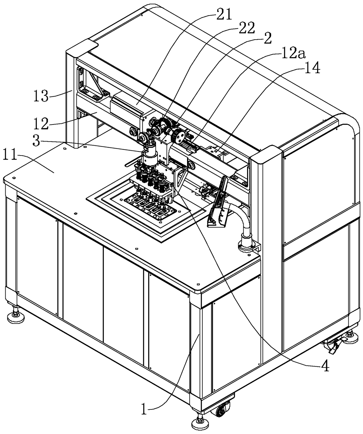
[0027] Such as figure 1 As shown, the frame structure of the punching machine of the present invention includes a frame 1 with a working surface 11 . A cross arm 12 for installing the punching mechanism is arranged above the work surface 11 , and both ends of the cross arm 12 are fixedly connected with the frame 1 through support arms 13 .

[0028] The cross arm 12 is provided with a driving mounting seat 2 which can move linearly along the cross arm 12, and the driving mounting seat 2 is provided with a punching knife connecting seat 3 which is driven by a punching power motor 21 and can move up and down. A punching knife mounting base 4 fixedly connected to the cross arm 12 is provided below the driving mounting base 2 , and at least two punching knife mounting rods 41 arranged side by side are arranged on the punching knife mounting base 4 . The lower end of each punching knife mounting rod 41 can be connected with a punching knife 45 for punching holes of various styles. ...

Embodiment 2

[0065] Such as Image 6 with Figure 7 Shown is another embodiment of the punching knife connection structure. In this embodiment, the punch connection structure also includes an interface seat 32 capable of connecting and detaching from the punch installation rod 41 , and the interface seat 32 is provided with two claws 33 capable of engaging both sides of the punch installation rod 41 . A connecting cylinder 34 is provided on the punching knife connecting seat 3 to drive the claw 33 to rotate to realize the engaging or releasing action.

[0066]The jaw 33 has a rotating portion 33a that is rotatably connected to the punching knife connecting seat 3 through a rotating shaft 35 , an engaging portion 33b that rotates around the rotating shaft 35 to open and close, and a cylinder connecting portion 33c that drives the claw 33 to rotate.

[0067] A groove 34a is formed at the end of the driving rod connected to the cylinder 34, and the cylinder connecting portion 33c is located...


PUM


Abstract

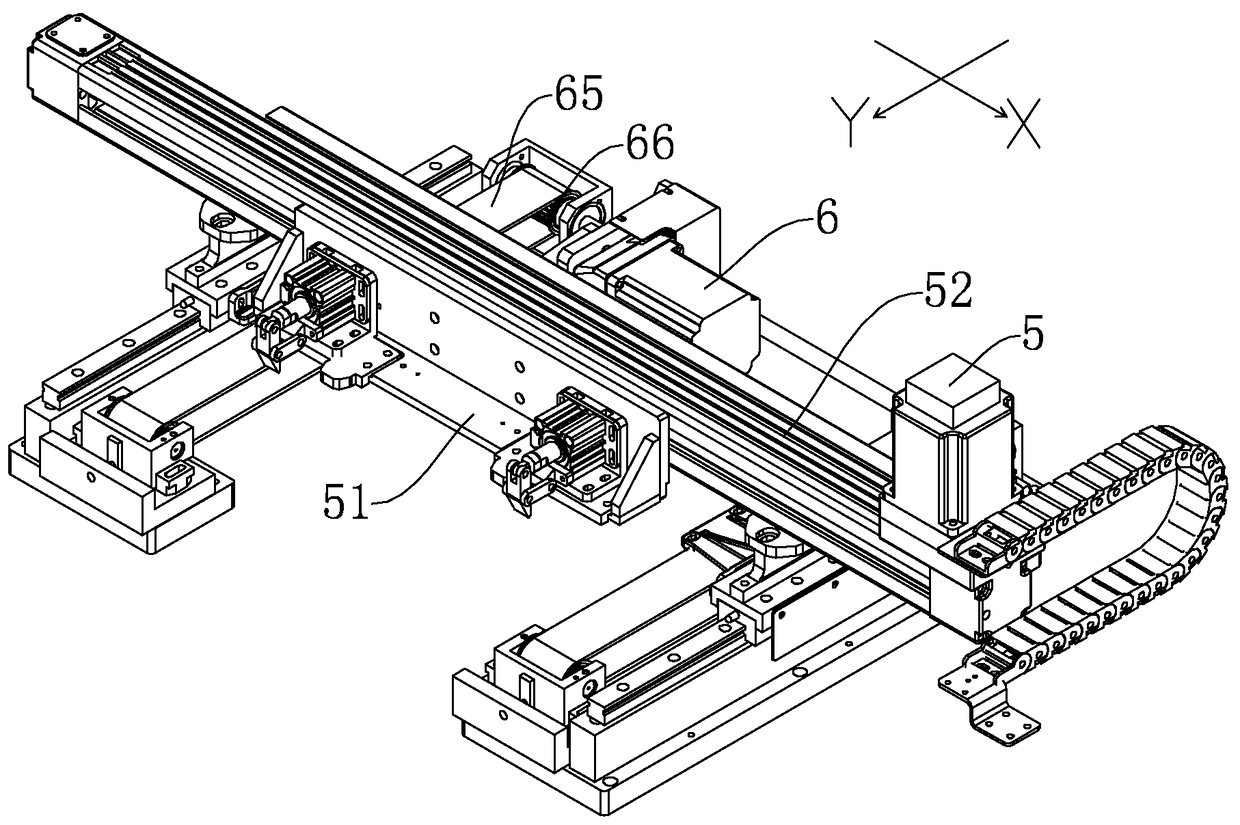
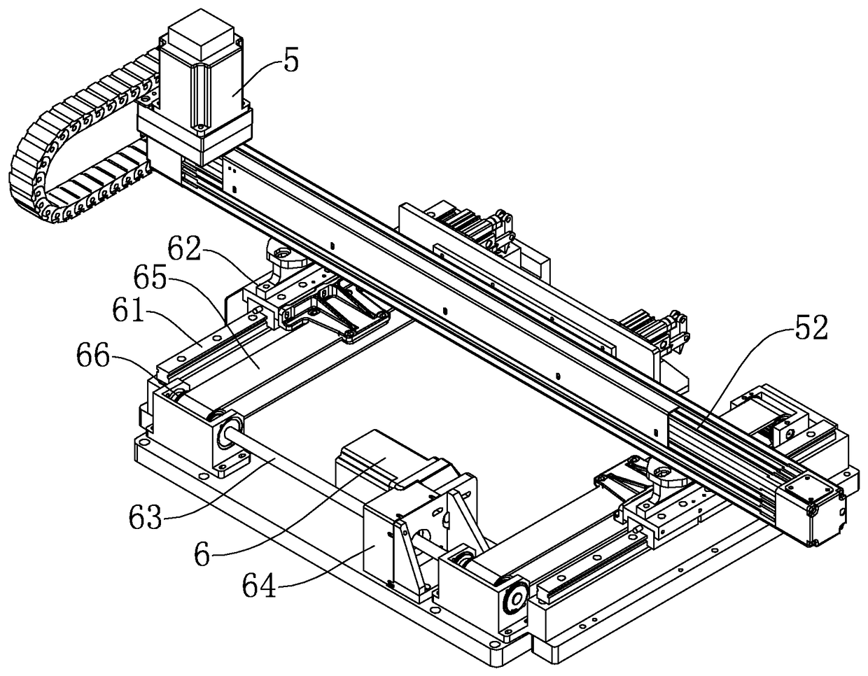
The invention discloses a full-automatic punching machine. The full-automatic punching machine comprises a machine frame with a working table surface, a driving mounting seat capable of moving linearly is arranged on a cross arm above the working table surface, a punching knife connecting seat which is driven by a punching power motor and capable of moving up and down is arranged on the driving mounting seat, a punching knife mounting seat which is fixedly connected with the cross arm is arranged below the driving mounting seat, at least two punching knife mounting rods which are arranged sideby side are arranged on the punching knife mounting seat, the working table surface is provided with a material clamping seat used for clamping materials and sending to-be-punched positions of the materials to a punching position, and a material feeding control module used for controlling the material clamping seat to move. According to the full-automatic punching machine, the punching knife connecting seat driven by the punching power motor is adopted, and the high rotation speed of the punching power motor is utilized so that the punching operation speed can be effectively increased.

Description

technical field [0001] The invention relates to punching equipment in the fields of clothing, luggage, and footwear processing, in particular to a full-automatic punching machine for punching holes on thin materials such as cloth and leather. Background technique [0002] In the fields of clothing, luggage, and footwear processing, it is often necessary to punch thin materials such as cloth and leather. Invention patent name: A non-woven fabric punching and forming device, patent application number: 201010202137.7 discloses a non-woven fabric punching and forming device, which includes a pneumatic punching device, a knife die device, an electric transmission device and a motor box, Pneumatic stamping device is arranged on the upper part of the device, die cutting device is connected to the lower part of the pneumatic stamping device, the die cutting device is supported and connected on the top platform of the motor box, and the electric transmission device is arranged on the...

Claims


Application Information

Patent Timeline
IPC IPC(8): B26F1/14B26D7/26B26D5/08B26D7/06
CPCB26D5/08B26D7/06B26D7/2614B26F1/14
Inventor 罗千
Owner NINGBO SUPREME ELECTRONIC MASCH INC
Learn More