
Band saw numerical control four-tooth stamping machine

A gear punching machine and band saw technology, applied in the field of band saw CNC four-tooth gear punching machine, can solve the problems of band saw material slippage, large mold loss, high production cost, etc., achieve accurate tooth pitch, improve production efficiency, and improve punching The effect of tooth speed

Active Publication Date: 2014-04-23
东莞市长盛刀锯有限公司
View PDF5 Cites 0 Cited by
  • Summary
  • Abstract
  • Description
  • Claims
  • Application Information

AI Technical Summary

Problems solved by technology

[0002] At present, the general production process of cutting band saw materials is as follows: first install the heat-treated band saw material on the gear cutting machine, and then install a single tooth cutting mold on the gear cutting machine to carry out tooth cutting; the band saw material The transmission is mainly driven by the ratchet installed on the gear cutting machine. Since the movement of the ratchet is mainly driven by the crankshaft drive of the gear cutting machine to adjust the tooth pitch, the structure is quite cumbersome; and the loss of the mold is large. The back of the tooth is easy to produce the phenomenon of band saw material slipping, the precision of the product is not high, and only single-tooth stamping can be carried out, which is time-consuming and laborious, and the production cost is high

Method used


Image

  • Band saw numerical control four-tooth stamping machine
  • Band saw numerical control four-tooth stamping machine
  • Band saw numerical control four-tooth stamping machine

Examples


Embodiment Construction

[0014] The present invention will be further described below with reference to the accompanying drawings.

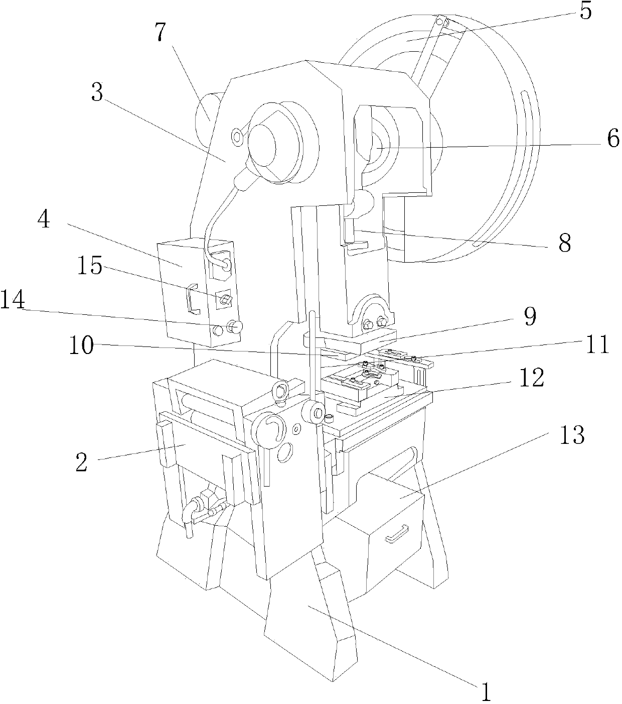
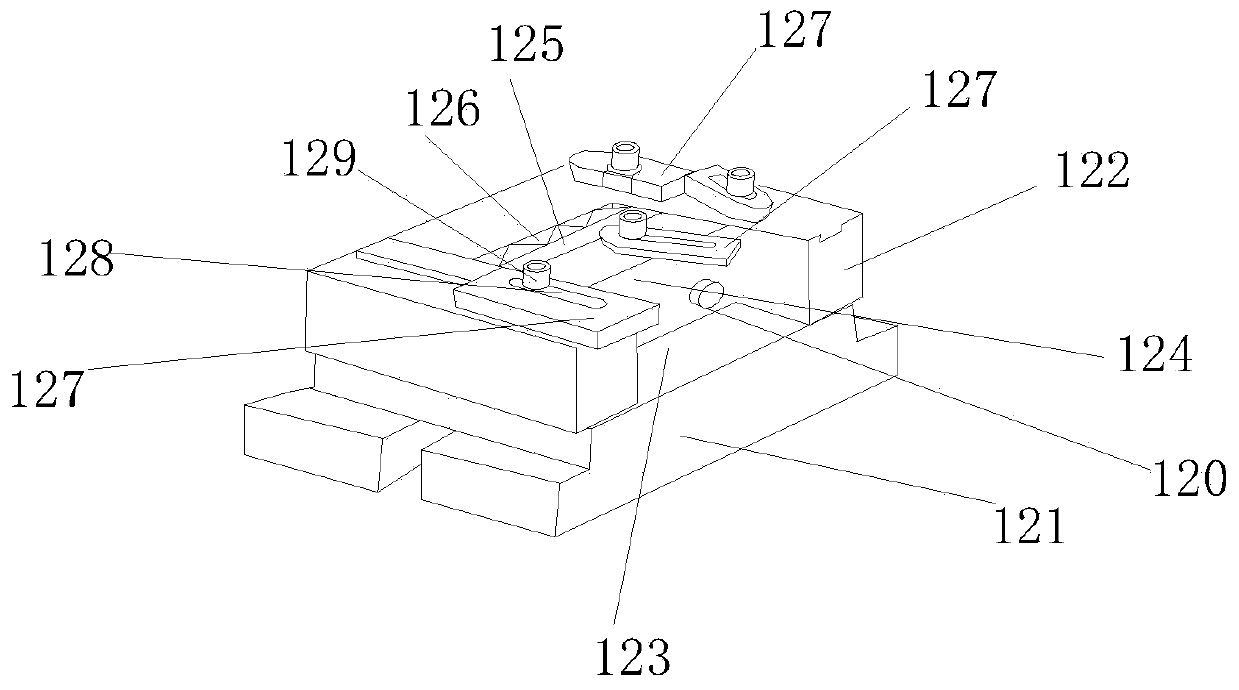
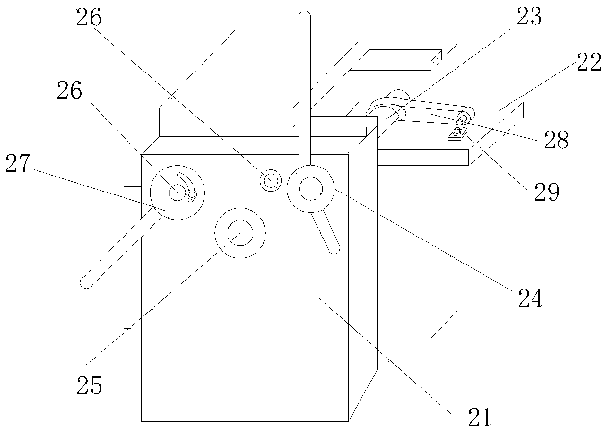
[0015] Such as figure 1 As shown, a band saw CNC four-tooth punching machine includes a CNC machine 1, a traction device 2 is provided on the left side of the CNC machine 1, and a CNC stamping support arm 3 is provided on the rear side of the CNC machine 1. One side of the support arm 3 is provided with an electric control box 4, and the other side of the CNC stamping support arm 3 is provided with a stamping gravity wheel 5, and the transmission shaft 6 of the stamping gravity wheel 5 is penetrated into the CNC stamping support arm 3, and is connected with the transmission The output shaft of the motor 7 is connected, and the middle part of the transmission shaft 6 extends vertically downwards to a pushing shaft 8. The end of the pushing shaft 8 is provided with an upper die mounting plate 9, and the lower end of the upper die mounting plate 9 is provided with an upper ...


PUM


Abstract

The invention discloses a band saw numerical control four-tooth stamping machine which comprises a numerical control machine table. The left side of the numerical control machine table is provided with a traction device, the rear side of the numerical control machine table is provided with a numerical control stamping supporting arm, one side of the numerical control stamping supporting arm is provided with an electric control box, and the other side of the numerical control stamping supporting arm is provided with a stamping gravity wheel. A transmission shaft of the stamping gravity wheel penetrates into the numerical control stamping supporting arm and connected with an output shaft of a driving motor, the middle of the transmission shaft vertically and downward extends to form a push-press shaft, an upper press mold installing plate is arranged at the end of the push-press shaft, an upper press mold is arranged at the lower end of the upper press mold installing plate, two sides of the upper press mold installing plate are respectively fixed through two sliding shafts, and a lower mold assembly is arranged right under the upper press mold. The band saw numerical control four-tooth stamping machine performs one-time stamping for one conveyed band saw section, tooth stamping distances of band saw sections are identical, tooth distances are accurate, edges and corners of saw teeth are clear, four teeth can be stamped in one time, the tooth stamping speed is greatly improved, and the production efficiency is improved.

Description

technical field [0001] The invention relates to the field of band saw manufacturing, in particular to a band saw numerical control four-tooth punching machine. Background technique [0002] At present, the general production process of cutting band saw materials is as follows: first install the heat-treated band saw material on the gear cutting machine, and then install a single tooth cutting mold on the gear cutting machine to carry out tooth cutting; the band saw material The transmission is mainly driven by the ratchet installed on the gear cutting machine. Since the movement of the ratchet is mainly driven by the crankshaft drive of the gear cutting machine to adjust the tooth pitch, the structure is quite cumbersome; and the loss of the mold is large. The back of the tooth is easy to produce the phenomenon of band saw material slipping, the precision of the product is not high, and only single-tooth stamping can be performed, which is time-consuming and laborious, and t...

Claims


Application Information

Patent Timeline
IPC IPC(8): B21D22/02
Inventor 张德华
Owner 东莞市长盛刀锯有限公司
Learn More