
Safe punch magnetic feeder

A safe feeder technology, which is applied in the field of mechanical stamping, can solve the problems of low-cost feeder stamping parts, inconvenient construction operations for workers, and affecting the production progress of workpieces, etc., to reduce the friction coefficient, easy to replace, and convenient to replace Effect

Inactive Publication Date: 2015-07-22
NANTONG INST OF TECH
View PDF6 Cites 0 Cited by
  • Summary
  • Abstract
  • Description
  • Claims
  • Application Information

AI Technical Summary

Problems solved by technology

[0002] Some small stamping parts are used in existing mechanical equipment. In existing machinery manufacturing factories, small stamping machines are used, such as 1T, 5T and 10T, etc., but such small punching machines have a larger The disadvantage is that safety devices are installed, and all stamping parts are placed manually
However, this method of operation is prone to the danger of crushing or breaking fingers
[0003] In actual stamping production, safety accidents caused by material feeding account for about 30%-38% of all accidents every year. Then some operators try to use metal tweezers to put stamping parts into stamping dies. Although this method is certain To a certain extent, the safety problem is solved, but it reduces the work efficiency and affects the production progress of the workpiece; then, in order to ensure the reduction of the incidence of safety accidents and the production efficiency of the workpiece at the same time, the existing feeding device has been used, but its complexity occupies a certain The space area is not convenient for workers to operate a set of safety feeding device, and it also increases the cost of the workpiece; there are also companies vying to develop a feeder for stamping parts, which is assembled from a solenoid valve type vacuum generator, a vacuum suction cup and related structural parts. The work of the vacuum generator is controlled by cutting off and on the power supply, and finally the workpiece is sucked by the vacuum chuck
However, in the actual production process, although the expected purpose can be achieved, because this device needs to be connected to a power source and an air source, the work site is relatively messy, and workers are subject to many restrictions in operation, which is not very convenient.
[0004] However, there is no simple, practical and low-cost feeder to meet the needs of domestic machinery factories for the safety performance of stamping parts.

Method used


Image

  • Safe punch magnetic feeder
  • Safe punch magnetic feeder
  • Safe punch magnetic feeder

Examples


Embodiment 1

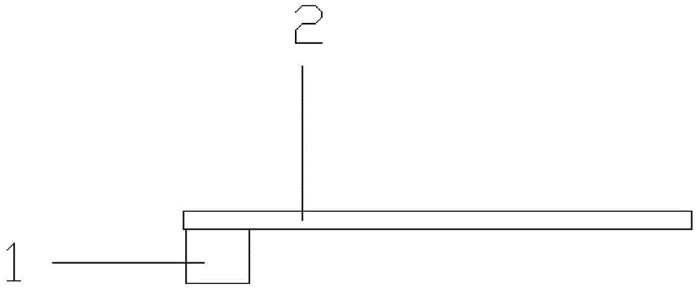
[0033] Such as Figure 1 to Figure 3 The shown magnetic feeder for a safety punching machine includes a permanent magnet 1 and a stick 2. The stick 2 is a wooden stick with a length of 200±10mm, including an A end and a B end, wherein the A end of the stick 2 is rectangular, and the bottom A permanent magnet 1 is installed; wherein the end B of the stick 2 is cylindrical.

[0034] The A end of the stick 2 can also be "fork-shaped" or "hook-shaped".

[0035] The permanent magnet 1 is cylindrical.

[0036] The permanent magnet 1 and the stick 2 are bonded by adhesive.

[0037] The upper surface of the stick 2 is sprayed with carbon nano-coating.

[0038] Described stick 2 can be changed into steel according to the demand of actual production.

[0039] The operation method of a safe type magnetic feeder for a punch press includes the following steps of bonding the permanent magnet 1 to the lower die of the punch press, the worker holds the end B of the stick 2 with the palm o...

Embodiment 2

[0041] Such as Figure 4 The shown magnetic feeder for a safety punching machine includes a permanent magnet 1 and a stick 2. The stick 2 is a wooden stick with a length of 200±10mm, including an A end and a B end, wherein the A end of the stick 2 is rectangular, and the bottom A permanent magnet 1 is installed; wherein the end B of the stick 2 is cylindrical.

[0042] The A end of the stick 2 can also be "fork-shaped" or "hook-shaped".

[0043] The permanent magnet 1 is cylindrical.

[0044] The permanent magnet 1 and the stick 2 are bonded by adhesive.

[0045] The upper surface of the stick 2 is sprayed with carbon nano-coating.

[0046] Described stick 2 can be changed into steel according to the demand of actual production.

[0047] The stick 2 is connected with the permanent magnet 1 at an included angle of 15° to 30° with the horizontal direction.

[0048] The operation method of a safe type magnetic feeder for a punch press includes the following steps of bonding ...

Embodiment 3

[0050] Such as Figure 5 The shown magnetic feeder for a safety punching machine includes a permanent magnet 1 and a stick 2. The stick 2 is a wooden stick with a length of 200±10mm, including an A end and a B end, wherein the A end of the stick 2 is rectangular, and the bottom A permanent magnet 1 is installed; wherein the end B of the stick 2 is cylindrical.

[0051] The A end of the stick 2 can also be "fork-shaped" or "hook-shaped".

[0052] There is a groove in the middle of the described stick 2 .

[0053] The permanent magnet 1 is cylindrical.

[0054] The upper surface of the stick 2 is sprayed with carbon nano-coating.

[0055] Described stick 2 can be changed into steel according to the demand of actual production.

[0056] The permanent magnet 1 and the stick 2 are bonded by adhesive.

[0057] The operation method of a safe type magnetic feeder for a punch press includes the following steps of bonding the permanent magnet 1 to the lower die of the punch press, ...


PUM


Abstract

The invention discloses a safe punch magnetic feeder which comprises a permanent magnet and a rod. The rod is a wood rod 200+ / -10 mm long. The rod comprises an end A and an end B, wherein the end A of the rod is rectangular, the permanent magnet is arranged at the bottom end of the rod, and the end B of the rod is cylindrical. During punching, a workpiece to be punched is placed on the safe punch magnetic feeder and falls into a punch lower die to be punched under the magnetic effect of the permanent magnet. Thus, by means of the safe punch magnetic feeder, the workpiece production efficiency is ensured, and the operation safety coefficient of workers is increased; meanwhile, the safe punch magnetic feeder is easy and convenient to operate, easy to replace, low in cost, easy to manufacture and convenient to use.

Description

technical field [0001] The invention belongs to the field of mechanical punching, and in particular relates to a safe magnetic feeder for punching machines. Background technique [0002] Some small stamping parts are used in existing mechanical equipment. In existing machinery manufacturing factories, small stamping machines are used, such as 1T, 5T and 10T, etc., but such small punching machines have a larger The disadvantage is that safety devices are installed, and all stamping parts are placed manually. However, this method of operation is prone to the danger of crushing or breaking fingers. [0003] In actual stamping production, safety accidents caused by material feeding account for about 30%-38% of all accidents every year. Then some operators try to use metal tweezers to put stamping parts into stamping dies. Although this method is certain To a certain extent, the safety problem is solved, but it reduces the work efficiency and affects the production progress of ...

Claims


Application Information

Patent Timeline
Patent Type & Authority Applications(China)
IPC IPC(8): B21D43/18
CPCB21D43/18
Inventor 卑五九王昌国林盛昌
Owner NANTONG INST OF TECH
Learn More