
Electric compressor

An electric compressor and electric technology, applied in the direction of machines/engines, mechanical equipment, liquid variable capacity machinery, etc., can solve problems such as high-level electromagnetic noise, increased loss, unbalanced rotating magnetic field, etc., to reduce stator vibration and improve Rigid effect

Inactive Publication Date: 2006-04-19
PANASONIC APPLIANCES REFRIGERATION DEVICES SINGAPORE
View PDF2 Cites 0 Cited by
  • Summary
  • Abstract
  • Description
  • Claims
  • Application Information

AI Technical Summary

Problems solved by technology

[0012] However, in the structure of the prior art described above, there is a problem that although the clamping portion 9 of the stator core 6 and the corner portion 12 near the bolt holes are relatively rigid, the gap between the stator iron plate 10 on the side portion 11 of the stator core 6 is relatively rigid. The gap is not fixed, and it is easy to become a floating state. As a result, due to the electromagnetic excitation force generated together with the generated rotating magnetic field, the stator iron plate with low rigidity vibrates alone, resulting in a high level of electromagnetic noise.
On the other hand, although the clamping part 9 has the function of stacking and fixing the stator iron plates 10 by pressing and stacking the extrusion protrusions 9a, when the extrusion protrusions 9a are pressed in, the stator Friction between the surfaces of the iron plates 10 causes insulation breakdown at the clamping portion 9, and the stator iron plates 10 are partially electrically connected
[0015] Furthermore, there is another problem that since the clamping portion 9 exists in the part where the magnetic flux density forming the rotating magnetic field is the highest, in the above structure, dielectric breakdown occurs in the part where the magnetic flux density is the highest, and as a result, a strong eddy current Flow to the adjacent stator iron plate 10, causing a large increase in loss, which significantly reduces the efficiency of the electric component 4
[0016] Another problem is that, due to the position of the clamping part 9, sometimes the pressing protrusion 9a of the clamping part 9 is pushed by the butt joint of the end block 14 of the stator core 6, and the stator core 6 is deformed at this time, and the air gap 19 becomes Inhomogeneity, resulting in an imbalance of the rotating magnetic field, generating large electromagnetic vibrations on the electric component 4

Method used


Image

  • Electric compressor
  • Electric compressor
  • Electric compressor

Examples


Embodiment Construction

[0030] Hereinafter, embodiments of the compressor of the present invention will be described with reference to the drawings. In addition, the same structure as the prior art is attached with the same code|symbol, and detailed description is abbreviate|omitted.

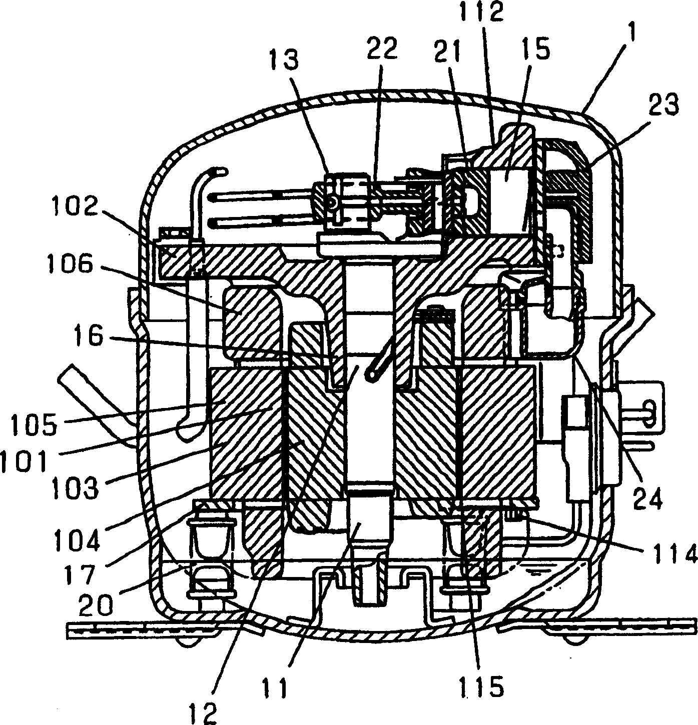
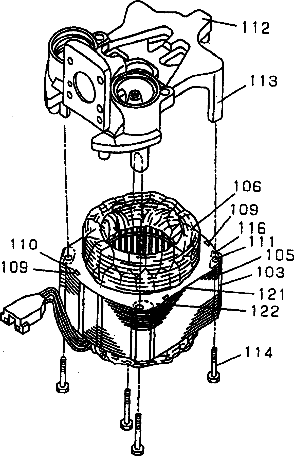
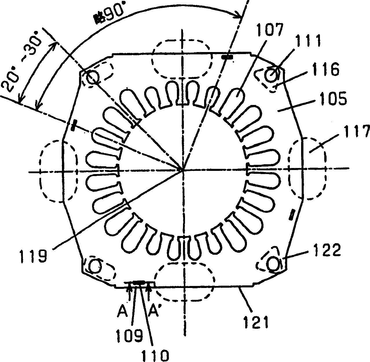
[0031] figure 1 It is a longitudinal sectional view of the first embodiment of the electric compressor of the present invention, figure 2 is an exploded perspective view of an end block, stator and penetrating bolts of the same embodiment, image 3 is a top view of the stator core of the same embodiment, Figure 4 for image 3 Sectional view at A-A' of . in addition, Figure 5 It is a plan view of the stator core of the electric compressor 2nd Embodiment of this invention.

[0032] Figure 1 to Figure 5 In the container 1, a motor assembly 101 and a compression assembly 102 are accommodated, and the motor assembly 101 is composed of a stator 103 and a rotor 104 . The stator 103 is composed of a stator core 10...


PUM


Abstract

The invention discloses a electric compressor can suppress electromagnetic noise generated by a motor element and improve its efficiency. A stator constituting the motor-driven element includes a stator iron core which is made of stator iron sheets of a rough square form in an outer periphery entangled and stacked each other by clamps of extruded projections and a coil interposed into a bag type slot formed on an inner periphery of the stator iron core, wherein the stator is fixed by a through bolt to a leg provided at a block, and the extruded projections are provided at a position near the outer periphery of the stator iron core except at a contact part with a leg's end face and the near central part of each side of the stator iron core, by which the electromagnetic noise caused by strain of the stator iron core and decline in efficiency caused by the extruded projections are reduced.

Description

technical field [0001] The present invention relates to a stator of an electric compressor used in refrigerators, air conditioners, freezers, and the like. Background technique [0002] In recent years, there has been a strong demand for high efficiency and low noise in electric compressors used in refrigeration equipment and the like. [0003] As a conventional compressor, there is a compressor described in US Patent No. 5,228,843 or Japanese Unexamined Patent Publication No. 60-66240. [0004] Hereinafter, the above-mentioned conventional electric compressor will be described with reference to the drawings. [0005] Figure 6 It is a longitudinal sectional view of an electric compressor in the prior art. Figure 7 is the plan view of the prior art stator iron plate, Figure 8 yes Figure 7 The cross-sectional view at X-X' of Figure 9 It is a cross-sectional view of the mold structure of the final blanking process of the stator iron plate in the prior art. [0006] ...

Claims


Application Information

Patent Timeline
Patent Type & Authority Patents(China)
IPC IPC(8): H02K1/18F04B35/04F04B39/00
Inventor 梅冈郁友松本刚八木章夫
Owner PANASONIC APPLIANCES REFRIGERATION DEVICES SINGAPORE
Learn More