
Blow moulding shaping apparatus

A technology of blow molding and components, which is applied in the direction of household appliances, hollow objects, and other household appliances, etc. It can solve the problems of increasing the workload of forming operation managers, difficulty in finding the correct position of conveying parts, and misalignment of conveying parts, etc., to achieve Improved dimensional accuracy, easy positioning, and reduced manufacturing costs

Inactive Publication Date: 2006-04-26
NISSEI ASB MASCH CO LTD
View PDF2 Cites 0 Cited by
  • Summary
  • Abstract
  • Description
  • Claims
  • Application Information

AI Technical Summary

Problems solved by technology

[0009] Therefore, when an attempt is made to prevent the horizontal rotation of the conveying member during conveyance by applying tension to the conveyer chain, the conveyer chain is worn and the life of the conveyer chain is shortened.
[0010] Furthermore, when the conveyor chain becomes longer due to wear and tear, the position of the conveyor components will also be misaligned, making it difficult to locate the conveyor components
Therefore, the management of the tension of the conveyor chain will become an important daily inspection item, increasing the workload of the forming operation manager

Method used


Image

  • Blow moulding shaping apparatus
  • Blow moulding shaping apparatus
  • Blow moulding shaping apparatus

Examples


Embodiment Construction

[0046] Hereinafter, embodiments to which the method and apparatus of the present invention are applied will be specifically described with reference to the drawings.

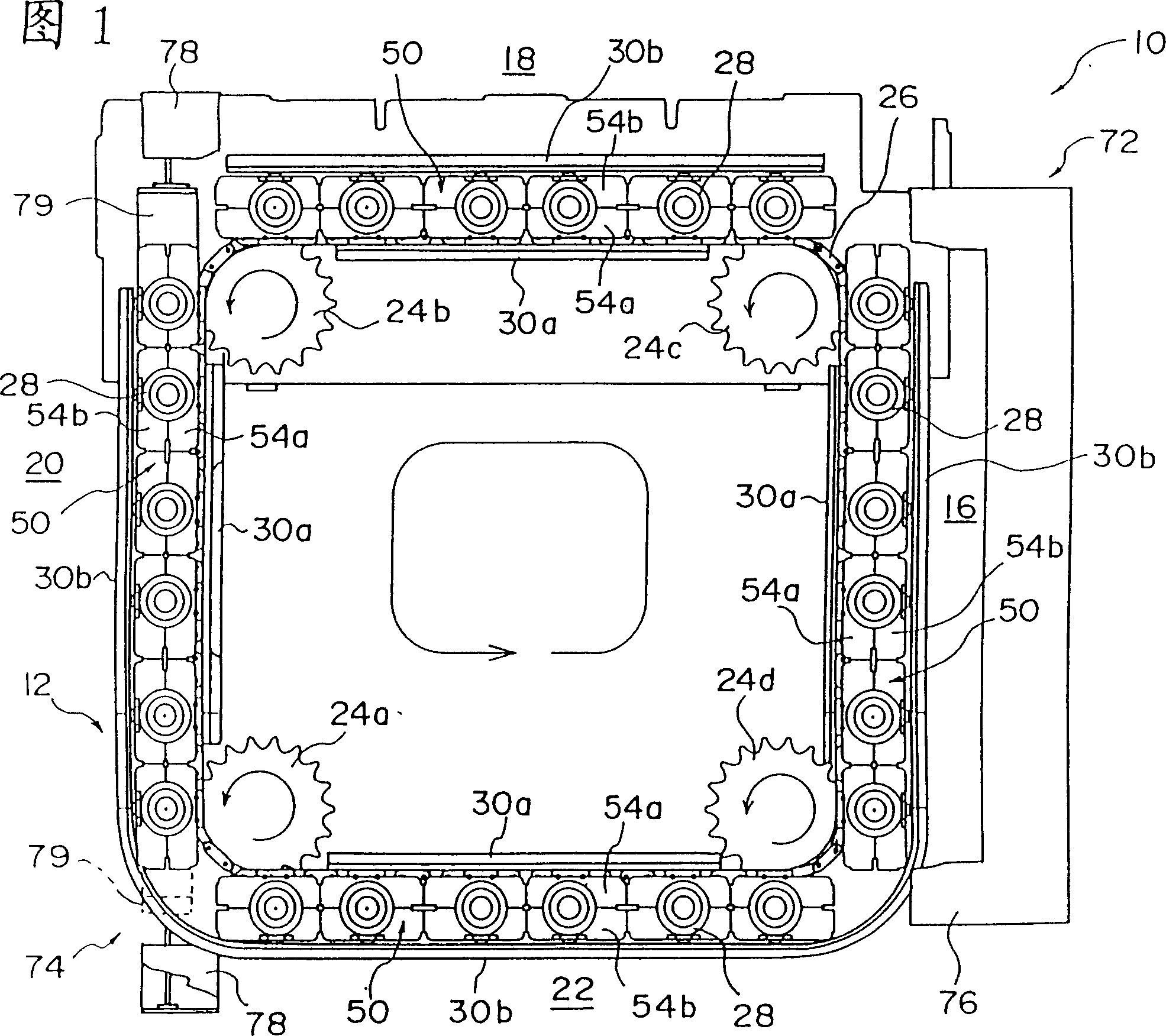
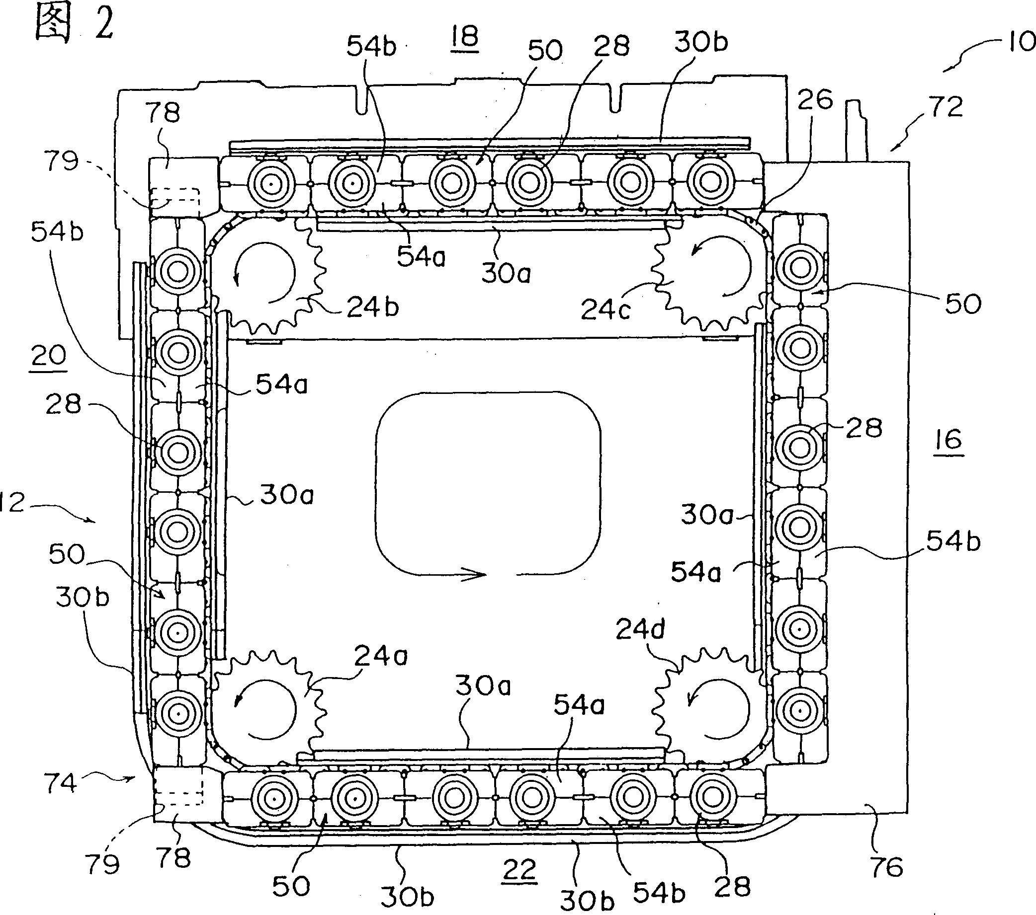
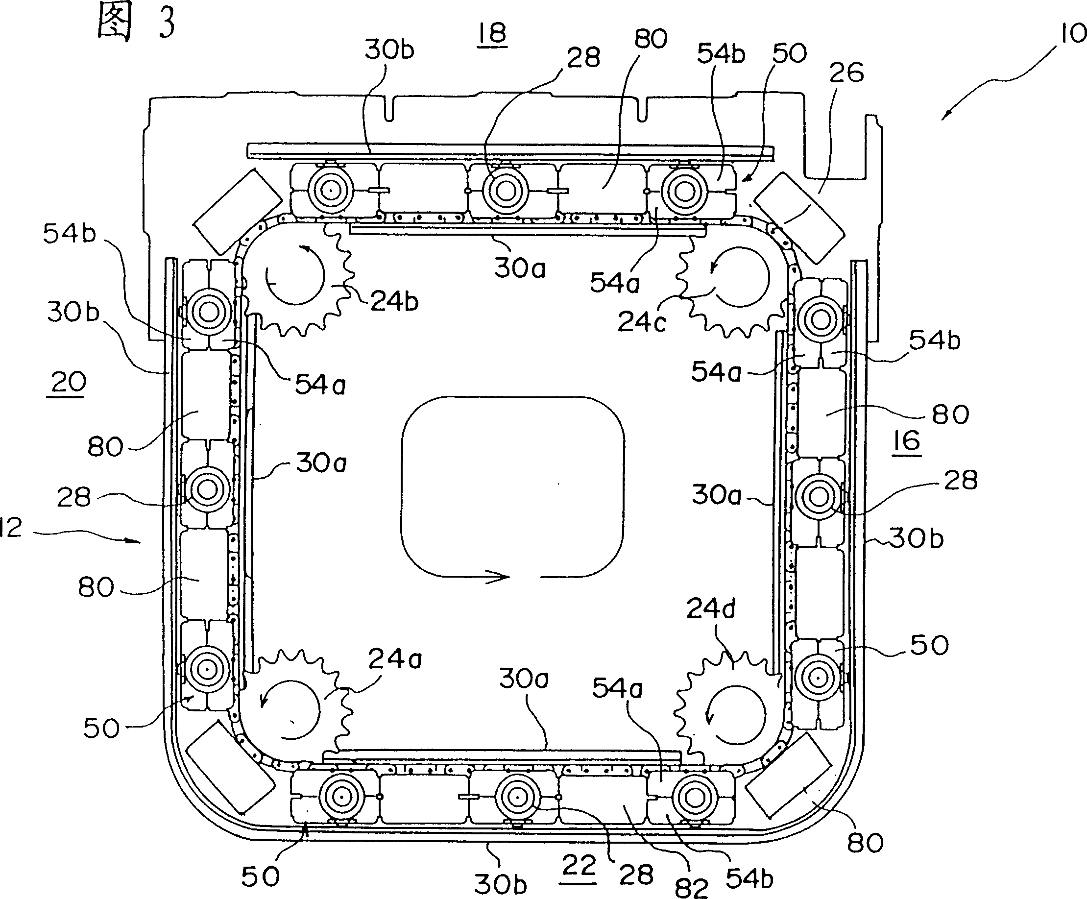
[0047] 1 and 2 are diagrams showing a blow molding apparatus according to an embodiment of the present invention. The details of each operation unit are omitted here because they have already been shown in Japanese Patent Laid-Open No. 8-132517 and No. 8-224775 related to the applicant's application.

[0048] The blow molding device 10 is provided with a substantially square conveyance path 12 , and four linear portions of the conveyance path 12 are respectively used as working sections.

[0049] And, on the 4 linear parts as these working sections, respectively are arranged: the receiving part 16 that is used to receive the preform 14 (referring to Fig. 5); The heating part 18 suitable for the temperature of blow molding; the blow molding part 20 that blows molds the preform 14 heated in the heating part 18 in...


PUM


Abstract

A blow molding device comprising: a plurality of conveying parts holding a preform; a conveying chain for driving the conveying parts, fixing the plural conveying parts at predetermined intervals; ) to guide rails in the direction of the blow molding section (20). Each conveying member has a covering member or a posture restricting member that can contact each other to cover the space between the conveying members or to prevent the horizontal rotation of each conveying member during conveying. Alternatively, it is possible to prevent horizontal rotation of the conveying member while conveying without applying tension to the conveying chain.

Description

[0001] This application is a divisional application of the application number 99103682 filed by the applicant on March 12, 1999. 4. The application titled "Blow Molding Device". technical field [0002] The present invention relates to a blow molding device, in particular to a blow molding device for conveying molded products by a conveying member fixed on a conveying chain. Background technique [0003] As a blow molding machine that heats a preform made of synthetic resin and then blows molds it into a predetermined container shape, in "JP-A-8-132517" and "JP-A-8-224775" previously proposed by the applicant, It was shown in the Bulletin. [0004] On the blow molding machine, the conveying path of the preform is formed into a square shape, and the heating part and the blow molding part are arranged on the straight part, and the preform is conveyed to the heating part and the blow molding part along the conveying path by the conveying device. On the blow molding part. [0...

Claims


Application Information

Patent Timeline
Patent Type & Authority Patents(China)
IPC IPC(8): B29C49/38B29C49/42B29L22/00
Inventor 荻原修一
Owner NISSEI ASB MASCH CO LTD
Learn More