
Atmospheric density-dependent power adjustment for wind turbines

A technology of wind energy equipment and control devices, which is applied in the control of wind turbines, the monitoring of wind turbines, and wind power generation, and can solve problems such as the decrease in rotor speed

Inactive Publication Date: 2006-05-10
阿洛伊斯沃本
View PDF1 Cites 0 Cited by
  • Summary
  • Abstract
  • Description
  • Claims
  • Application Information

AI Technical Summary

Benefits of technology

This innovation improves upon existing structures that use an external measurement system or sensors like pneumatic tonometers (pistons) attached to a pipe carrying fluid). By doing things similar to how these systems work, we don't require any adjustments during installation but instead they are able to measure both pressures and temperatures accurately.

Problems solved by technology

Technological Problem addressed in this patents describes how an efficient way to manage a wind turbine's performance during different stages or conditions such as low altitude flying maneuvers (LFM) with reduced levels of atmospheric pressure.

Method used


Image

  • Atmospheric density-dependent power adjustment for wind turbines
  • Atmospheric density-dependent power adjustment for wind turbines

Examples


Embodiment Construction

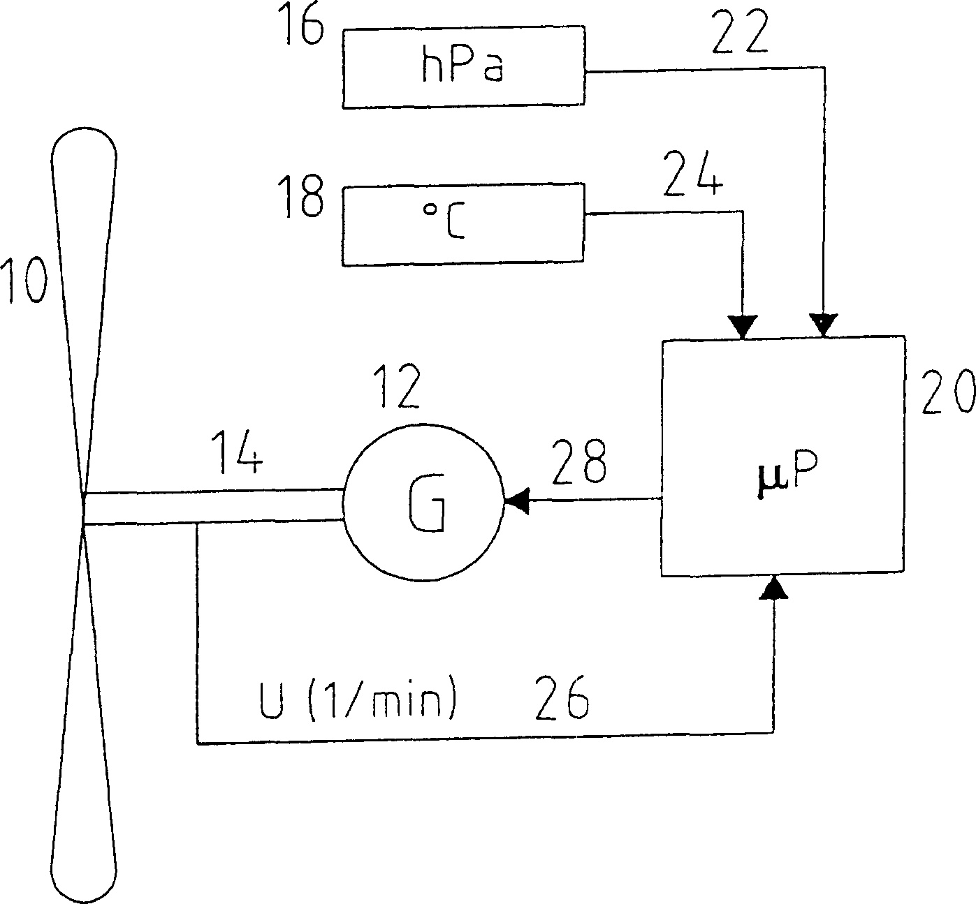
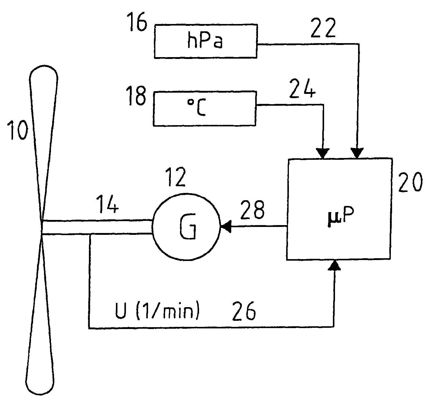
[0029] The figure depicts a wind energy plant with a rotor 10, a generator 12, an energy transfer mechanism 14 between the rotor and the generator, a device 16 for measuring air pressure, a device 18 for measuring temperature and A control unit 20 with a microprocessor.

[0030] The device 16 for measuring air pressure is connected to the control device 20 via a connection 22 , the device for measuring temperature is connected to the control device via a connection 24 , and transmits the rotor speed to the control device 20 via a connection 26 . This connection can be, for example, an electrical connection wire, or other suitable connection means, such as a wireless communication link.

[0031] The control device 20 determines the output power of the generator from the transmitted information on the basis of predetermined power data and influences the excitation power delivered to the generator 12 via a connection 28 .

[0032] In this case, the mode of operation of the contr...


PUM


Abstract

The invention discloses a wind energy equipment with a control device for managing and running the wind energy equipment. The invention also discloses a method for controlling a wind energy equipment with a control device for managing the operation cycle. In order to extract as much energy as possible from the wind, the control device takes into account the altitude at which the wind energy installation is installed and/or the height of the wind energy installation. Furthermore, the method according to the invention measures the air density and transmits a signal characterizing the air density derived from the measured air density value to the control device for consideration by the control device when managing the operation.

Description


Claims


Application Information

Patent Timeline
Owner 阿洛伊斯沃本
Learn More