Thaw plate system

a technology of thaw plates and thaw plates, which is applied in the field of thaw plate systems, can solve the problems of food poisoning, limited use of conventional thaw plates, and temporal bottleneck in this process, and achieve the effects of reducing costs, prohibitive expense, and better ability to clean the uni

Inactive Publication Date: 2010-01-21
DAKA RESEARCH INC
View PDF0 Cites 10 Cited by
  • Summary
  • Abstract
  • Description
  • Claims
  • Application Information

AI Technical Summary

Benefits of technology

[0018]Another advantage of the invention is the de-couple ability of the cold plate such that the air blowing unit is removable from engagement with the cold plate. This gives the advantages of reduced cost in not having to provide for a completely immersible unit, a better ability to clean the unit. Without separability, a motor unit could become soiled if juices from meat or other thawing foods runs into it. Whilst motor units can be waterproofed, this added expense is prohibitive in the ability to provide the advantage of a low cost product.
[0019]A further way to reduce the cost of the product is to utilize any flat surface as the wall which lies opposite the heat transfer plate in order to provide a ducted passage through which the air flows. The tray sits on a flat surface to create a slight gap for the blower to blow air underneath the tray and out through an exhaust gap on the opposite edge for air to exit. The thawing food support tray also preferably may have a detail to catch drips all the way around and may also have a slight incline so that juices on the aluminum plate, should they collect, will flow away from the blower unit. An optional cover may also supplied to allow the user to cover the food being thawed and thereby keep flying insects and airborne contaminants off the food as it thaws, an especially useful feature for use out of doors. A cover shown can preferably fit beneath the tray for compact storage and shipping. For cleaning, the blower unit is simply removed and the tray, cover and aluminum plate can be immersed for washing.

Problems solved by technology

However there is a temporal bottleneck in this process as most frozen food needs to be defrosted before it can be cooked.
This method of thawing is disadvantageous as it is slow, causing the user to place the food at room temperature for a long time before cooking, because preparers are typically more worried about not having the food thawed in time more than they worry about the possibility that the food is exposed to room temperature for an extended time.
This can result in food poisoning.
A further method is to use a thaw plate that accelerates the transfer of heat energy by conduction, but conventional thaw plates have some limitations.
Cooking the food while in this condition may produce top and sides which are perfectly done but a significant volume within the food mass which is raw and can cause parasites and disease if the food is consumed.
Thawing food left on a surface will give no outward indication that a significant mass is still frozen unless it is probed and its temperature measured throughout, which is impractical an onerous.
Further, if the food has a significant volume which is still not thawed, and if the cooking process is on a deadline, a bad result will occur in any event.
Either the food will be cut up to free the thawed parts, or the food will be cooked anyway, which is dangerous.
One drawback of conventional thaw plates is that they rapidly develop a cold spot below the location where the thawing mass is placed.
The “cold spot” is due to the fact that the heat from the surrounding parts of the plate cannot flow fasten enough into the thawing mass.
This has a great effect on reducing the effectiveness of conventional thaw plates.
This device does not have a thaw plate support which can be disassembled for storage apart from the motor unit.
In essence, the plate and housing cannot be immersibly cleaned because the fan and motor cannot be detached from the housing without dis-assembly.
Further, this unit appears to have a heavy duty motor located underneath the thawing plate and may derive significant heat value from the motor.
In addition, this unit also appears to be a heavy stationary unit, and not portable.

Method used


Image

  • Thaw plate system
  • Thaw plate system
  • Thaw plate system

Examples


Embodiment Construction

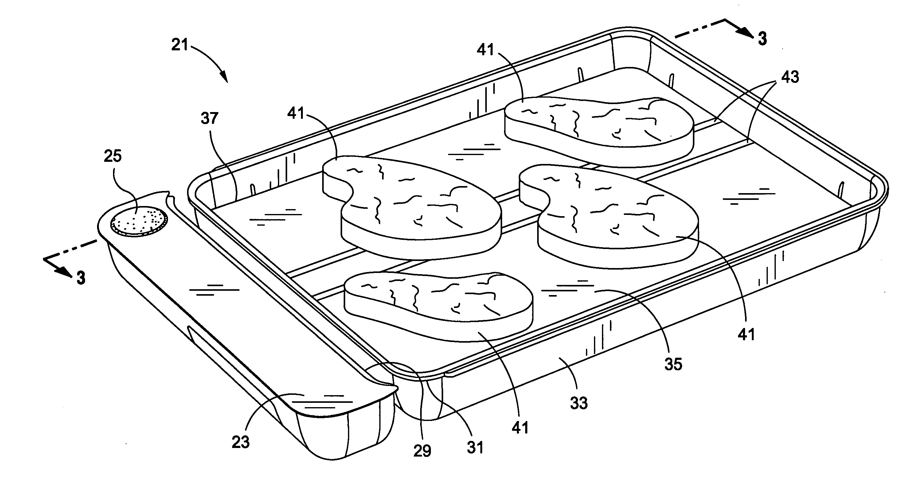
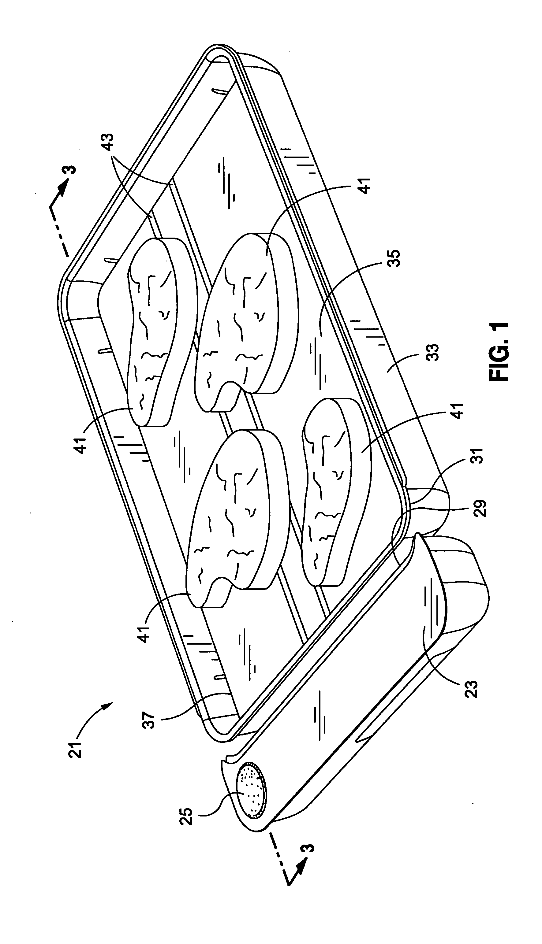
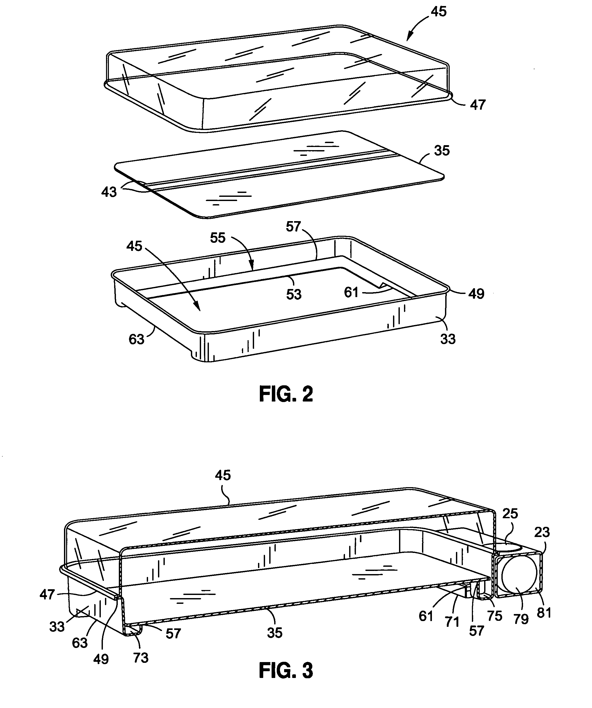
[0028]The description and operation of the thaw plate system 21 of the invention will be best described with reference to FIG. 1 which illustrates the assembled and operational thaw plate system 21 but without the cover (not shown) for clarity. The thaw plate system 21 includes a motor unit 23 shown partially spaced apart from the other structure to the right, and having an on / off button 25. The motor unit includes a concave curved portion 29 which mates with an edge and opposite convex curved portion 31 of a plate support tray 33. The number 33 is pointing at the outer wall of an overall “U” cross sectional shape of each side (as will be shown). The plate support tray 33 includes a thermally transmissive metal plate 35 which is preferably supported at an angle, having an upper end 37 showing a lesser height of plate support tray 33 above it, to a lower end 39 showing a greater height of plate support tray 33 above it.

[0029]Shown supported by the thermally transmissive metal plate 3...


PUM


Abstract

A thaw plate has a separate, self support motor unit which has an air exhaust which can be brought into proximity of an inlet opening of a plate support tray to cause air to flow underneath a thermal conduction plate in a manner that will cause thawing to occur. In a first embodiment a battery powered fan will cool the bottom of a thaw plate. The use of a fan to cause air to sweep across the bottom of the conduction plate will insure that enough flow will be present that the plate will not sweat or freeze. A second embodiment includes an air density chimney will be used to passively create a stream of air which will sweep a thermal conduction plate to create a warm air flow to enhance the thawing process in proportion to the difference in temperature between the thawing masses and the room temperature air.

Description

FIELD OF THE INVENTION[0001]The present invention relates to an improvements in providing a safe, effective, low cost device and method for thawing food which will enhance the consistency and flavor of the food while reducing the time before cooking to a minimum safe time based upon ambient air, and more particularly to a safe, low energy, battery operated device which is safe to use, can be left unattended and which enables the user to depend upon it in lieu of taking a quick action for thawing which can ruin the food.BACKGROUND OF THE INVENTION[0002]Cooks frequently freeze food, or buy frozen food, to greatly extend the period before which it becomes unsafe for consumption. Shoppers often buy food frozen for immediate preparation and consumption. The maintenance of a stock of frozen food also allows grocery stores and domestic and professional cooks great flexibility in what they will prepare for consumption on a daily basis. However there is a temporal bottleneck in this process ...

Claims


Application Information

Patent Timeline
Patent Type & Authority Applications(United States)
IPC IPC(8): A23L3/36F28D15/00
CPCA23L3/363
Inventor KALOGROULIS, ALEXANDER JOSEPH
Owner DAKA RESEARCH INC
Why Eureka
Try Eureka