Self lubricated non-sealed piston ring for IC engine fastener driving tool

A self-lubricating ring, non-sealing technology, used in pistons, piston rings, nail tools, etc., can solve problems such as adverse effects on market sales

Inactive Publication Date: 2006-05-17
ILLINOIS TOOL WORKS INC
View PDF0 Cites 0 Cited by
  • Summary
  • Abstract
  • Description
  • Claims
  • Application Information

AI Technical Summary

Problems solved by technology

This may in turn have a negative impact on the market for this tool

Method used


Image

  • Self lubricated non-sealed piston ring for IC engine fastener driving tool
  • Self lubricated non-sealed piston ring for IC engine fastener driving tool
  • Self lubricated non-sealed piston ring for IC engine fastener driving tool

Examples


Embodiment Construction

[0022] The following describes a non-sealed self-lubricating ring according to the present invention, a piston assembly using the non-sealing self-lubricating ring, and an internal combustion engine using the piston assembly. In the following detailed description, for the sake of explanation, many specific details are set forth in order to have a thorough understanding of the present invention. However, it will be understood that the present invention may not be implemented in accordance with these specific details. In other cases, some well-known structures and devices are schematically shown in order to simplify the drawings.

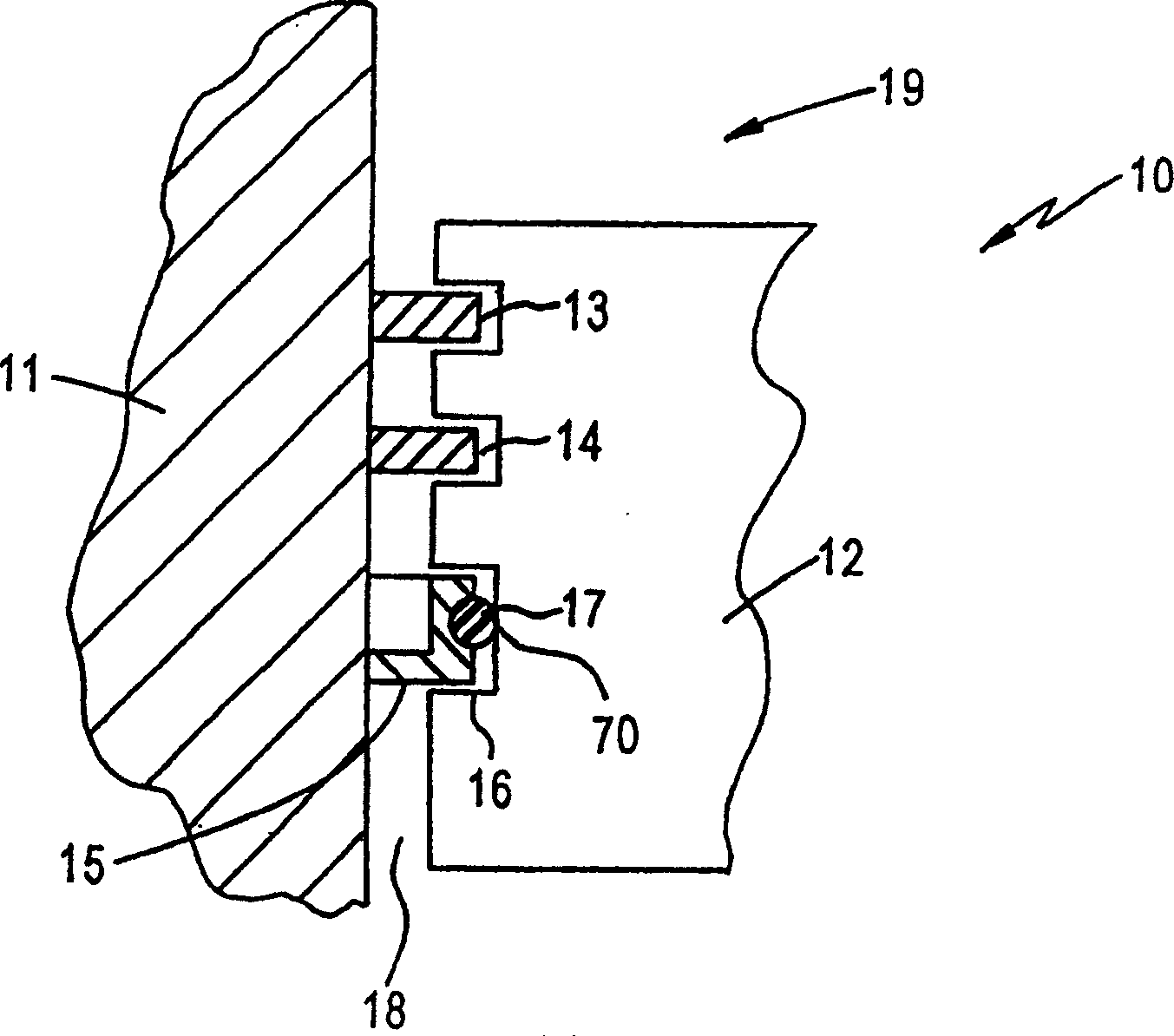
[0023] Reference now figure 1 The figure shows an internal combustion engine 10. The internal combustion engine 10 includes a cylinder and a piston 12 that reciprocates. The cylinder includes a cylinder wall 11 and a cylinder head (not shown). The cylinder head, cylinder wall 11 and piston 12 together define a combustion chamber 19 into which fuel is inj...


PUM


Abstract

A non-sealing, lubricating piston ring (15) for lubricating the cylinder wall (11) of a piston housing in a combustion tool is disclosed. The lubricating piston ring (11) is made from a lubricating material such as polytetrofluroethylene (PTFE). The shape of the PTFE ring is designed to optimize the lubricity of the piston housing, while allowing enough friction for the piston (12) to operate properly within the piston housing during reciprocating cycling movement. The PTFE ring (20, 50, 60) may have radial fins (22, 52, 62) extending from an outer surface thereof that are angled to promote ring rotations, such that the ring moves easily along and efficiently lubricates the inner cylinder wall of the piston housing. The PTFE ring does not form a seal between the piston and the housing. Instead, the PTFE ring is positioned above or below a sealing ring, (13, 14) such as a steel piston ring which forms the seal between the piston and the piston housing.

Description

Technical field [0001] Generally speaking, the present invention relates to a piston ring used for lubricating the cylinder wall of a piston chamber in a fuel tool, and more specifically to a piston ring made of self-lubricating material. Background of the invention [0002] As we all know, commercially available piston rings can be made of wear-resistant and low-friction materials, such as self-lubricating materials, and molded into the shape of a self-lubricating sealed piston ring. Generally speaking, such piston rings are made of PTFE (polytetrafluoroethylene), which has a very low coefficient of sliding friction, high thermal stability and satisfactory wear resistance. In fact, PTFE rings are used in most cordless internal combustion engine driven pneumatic nailers and air compressors. The presence of the PTFE ring in the piston assembly of the internal combustion engine eliminates the need for external lubricant, and enables the internal combustion engine to run with lubric...

Claims


Application Information

Patent Timeline
Patent Type & Authority Patents(China)
IPC IPC(8): F02F5/00F02F3/04F16J9/00F16J9/28B25C1/08F16J9/20F16J9/26
CPCB25C1/08F02F5/00
Inventor 威廉罗伯茨克里斯H·波特
Owner ILLINOIS TOOL WORKS INC
Why Eureka
Try Eureka