
Antenna for portable mobile telephone

A wireless telephone and portable technology, applied in the direction of electric short antenna, antenna, folding antenna, etc., can solve problems such as resonance frequency shift and frequency band narrowing

Inactive Publication Date: 2006-05-24
HITACHI CABLE LTD
View PDF0 Cites 0 Cited by
  • Summary
  • Abstract
  • Description
  • Claims
  • Application Information

AI Technical Summary

Problems solved by technology

[0004] However, when using a conventional portable radiotelephone antenna, the antenna element 102 must have a certain height because the ground portion 101 of the printed circuit board is close to the antenna element 102, resulting in a narrow frequency band.
In addition, since the inverted F-shaped antenna is easily affected by the printed circuit board ground (circuit board ground), the position of the circuit board ground changes with the opening and closing of the upper housing and the lower housing like a foldable mobile phone. , its resonant frequency will shift

Method used


Image

  • Antenna for portable mobile telephone
  • Antenna for portable mobile telephone
  • Antenna for portable mobile telephone

Examples


Embodiment Construction

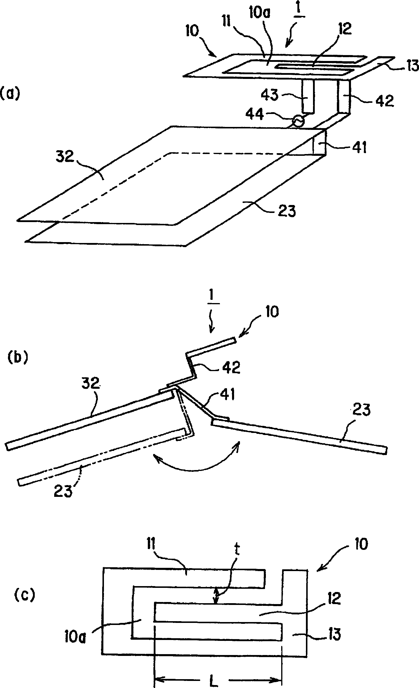
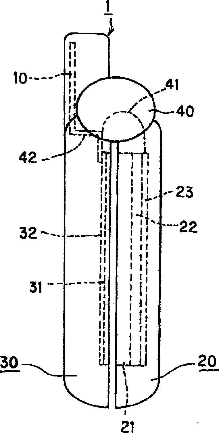
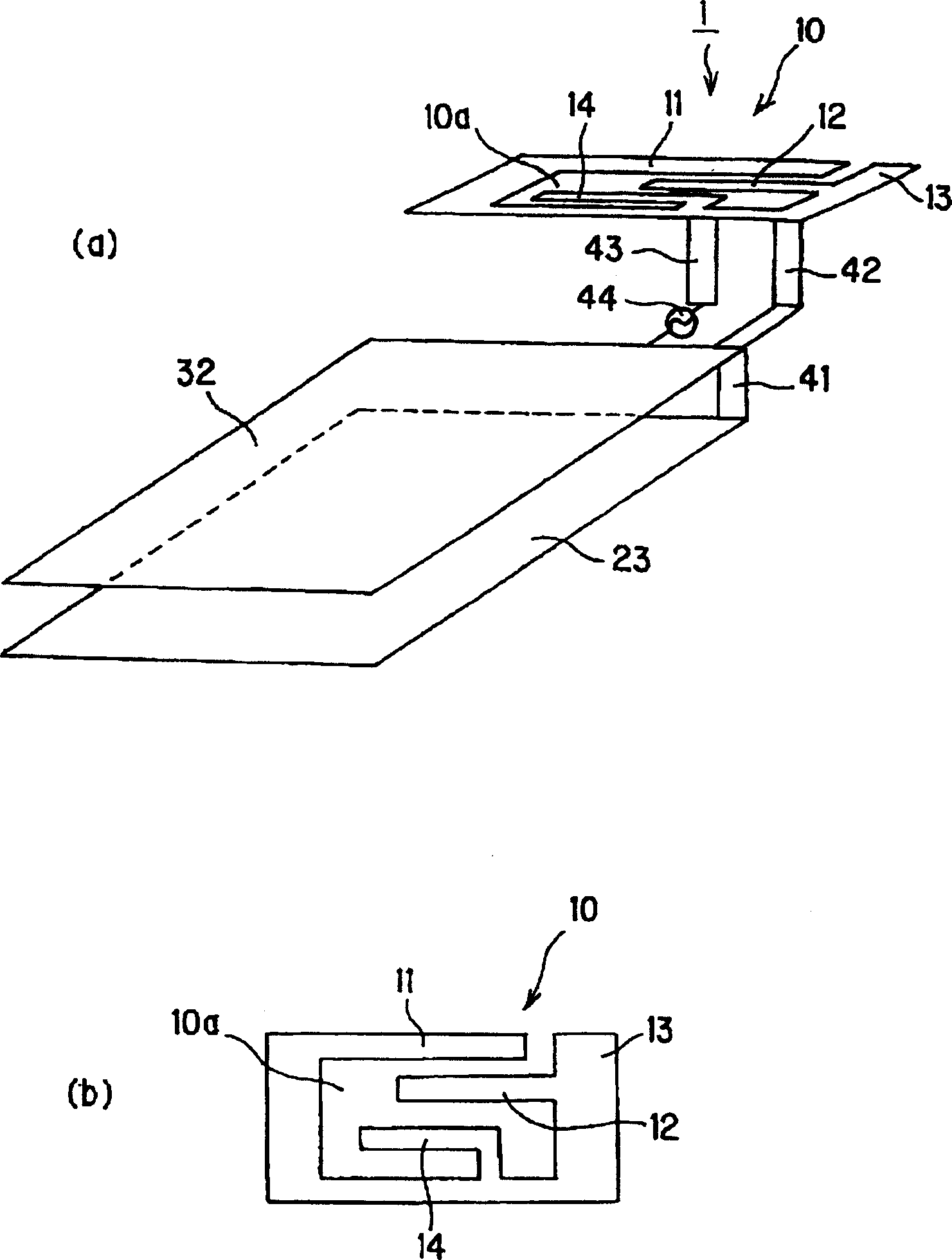
[0016] figure 1 (a) is a perspective view, (b) is a side view in an opened state, and (c) is a plan view of important parts. The portable radiotelephone antenna (hereinafter referred to as "antenna"), such as figure 1 As shown in (a) and (b), there are radiating element portion 10 excited at a constant resonance frequency, wiring board ground 32, and LCD ground 23. The radiation element part 10 and the circuit board ground wire 32 are connected through the ground wire connection part 42 , and the circuit board ground wire 32 and the LCD ground wire 23 are connected through the circuit board ground wire connection part 41 and can be switched. Further, a strip-shaped power supply member 43 is provided on the radiation element portion 10 to be adjacent to the ground connection portion 42 so as to hang down. The power supply point 44 is between the end of the power supply component 43 and the circuit board ground wire 32 .

[0017] Radiating element section 10, such as figu...


PUM


Abstract

This invention relates to antennas for portable radiotelephones. The antenna provided by the present invention can widen the frequency band without raising the position of the antenna element, and can suppress the shift of the resonance frequency even with a structure in which the position of the ground part is changed. Mounted on a portable wireless device such as a portable phone, the panel antenna (10) connected to the printed circuit board contained therein and the ground portion (32, 23) of the LCD forms a horizontal U shape as a whole, and has a main body The first radiating element (11) extending in a straight line and in a strip shape from one end thereof, the combination adjustment part (12) adjacent to the first radiating element and arranged in parallel on the same plane, and the end portion and combination of the first radiating element The second radiating element (13) connected to the adjustment part. In addition, a port part (43) for power supply is provided near the other end of the first radiating element, and a ground connection part (42) for connecting the circuit board ground (32) is provided at the end of the second radiating element.

Description

technical field [0001] The present invention relates to an antenna for a portable radiotelephone, particularly capable of widening its frequency band without elevating the position of an antenna element, and suppressing the use of a position-variable structure such as a circuit board ground wire in a foldable portable telephone or the like Portable radiotelephone antenna for resonant frequency error of the portable radiotelephone. Background technique [0002] Portable phones and PHS-Personal Handy-phone System (PHS-Personal Handy-phone System) phones are equipped with retractable whip antennas and built-in flat-panel antennas for smooth transmission and reception of signals with ground stations. The most representative panel antenna is an inverted F-shaped antenna with a small and simple structure and broadband characteristics. [0003] Figure 8 Indicates an antenna for a conventional portable radiotelephone. The inverted F-shaped antenna 100 as an antenna for this porta...

Claims


Application Information

Patent Timeline
Patent Type & Authority Patents(China)
IPC IPC(8): H01Q9/06H01Q1/36H01Q1/08H01Q1/24H01Q1/38H01Q5/10H01Q5/371H01Q9/04H01Q9/42
CPCH01Q1/08H01Q1/243H01Q9/0421H01Q9/0442H01Q5/371H01Q1/38H01Q1/48H01Q9/26H01Q9/42H01Q5/10H01Q5/40
Inventor 堀田均杉山刚博片冈慎高场进一
Owner HITACHI CABLE LTD
Learn More