Multi-frequency array antenna

An array antenna and radiation array technology, applied in the direction of antenna, antenna coupling, antenna array, etc., can solve problems such as difficulty in achieving optimization, the size cannot be further reduced, and the high frequency radiation characteristics are restricted.

Active Publication Date: 2018-05-01
COMBA TELECOM TECH (GUANGZHOU) CO LTD +1
View PDF10 Cites 0 Cited by
  • Summary
  • Abstract
  • Description
  • Claims
  • Application Information

AI Technical Summary

Problems solved by technology

[0003] One of the existing technologies: Kathrein-Werke KG company discloses a miniaturized antenna design method (US2006 / 00114168A1) of a nesting method, but the size of this method cannot be further improved in the case of three or more independent electric frequency bands. decrease
The second prior art: Huawei’s patent publication No. CN103050788A provides another design idea, which reduces the size of the overall antenna by placing the high-frequency antenna in the low-frequency radiation arm ring, but its The high-frequency radiation characteristics are limited by the low-frequency radiation arms surrounding the high-frequency radiation unit, and it is difficult to achieve optimum

Method used


Image

  • Multi-frequency array antenna
  • Multi-frequency array antenna
  • Multi-frequency array antenna

Examples


Embodiment 1

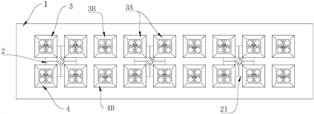
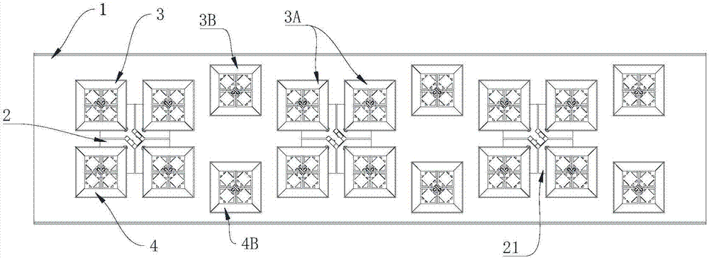
[0028] Arrangement of low-frequency radiation array and high-frequency radiation array on metal reflector

[0029] Please refer to Figure 1~3 , the array antenna includes a metal reflector 1 , and a low-frequency radiation array 2 and a high-frequency radiation array 3 and 4 installed on the metal reflector 1 . The low frequency radiation array 2 includes at least one low frequency radiation unit 21; the high frequency radiation arrays 3 and 4 respectively include at least one high frequency radiation unit.

[0030] Such as Figure 1~3 As shown, the metal reflector 1 is usually arranged as a vertical rectangle in order to adapt to the practical application of the mobile communication antenna, and several low-frequency radiation units 21 are arranged along the longitudinal direction of the metal reflector 1, thus defining the first Axis (not shown): an axis parallel to the longitudinal direction of the metal reflector 1 and passing through the centers of the several low-freq...

Embodiment 2

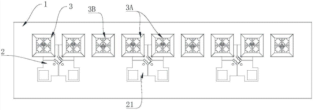
[0035] Structure of low frequency radiation unit and high frequency radiation unit

[0036] Taking the high-frequency radiation units 3A and 3B as examples, the structure of the high-frequency radiation units will be described in detail.

[0037] refer to Figure 4 and Figure 5, the structures of the high-frequency radiation units 3A and 3B are the same: including a high-frequency radiator 31 , a reflector 32 and a dielectric layer 33 . The high-frequency radiator 31 realizes the sending and / or reception of high-frequency radiation signals; the reflector 32 surrounds the high-frequency radiator 31 to form the radiation boundary of the high-frequency radiator 31, and A reflective cavity is formed around the high-frequency radiation body 31 to control the sending and / or receiving direction of the high-frequency radiation signal. In this embodiment, the upper end of the reflector 32 is open and the lower end is closed, and the diameter of the upper end of the reflector 32 is l...


PUM


Abstract

The invention discloses a multi-frequency array antenna, which includes a metal reflector and a low-frequency radiation array composed of at least one low-frequency radiation unit and a high-frequency radiation array composed of at least one high-frequency radiation unit arranged on the metal reflector, wherein , defining an axis parallel to the longitudinal direction of the metal reflector, at least one of the low-frequency radiation arrays is arranged along the axis; the low-frequency radiation unit includes at least one radiation arm, and the high-frequency radiation unit is arranged at Above the radiation arm of the low frequency radiation unit and / or between two low frequency radiation units. The multi-band array antenna of the invention effectively reduces the lateral size, has superior electrical performance, is convenient to install, and has high reliability.

Description

technical field [0001] The invention relates to a mobile communication antenna technology, in particular to a multi-frequency array antenna. Background technique [0002] With the gradual acceleration of the construction of the fourth-generation mobile communication network, operators began to look for super mobile phones that can be backward compatible with 2G and 3G standards such as GSM800, GSM900, DCS1800, PCS, CDMA1800, and CDMA2000, and can be upwardly compatible with 4G standards such as LTE700 and LTE2600. broadband antenna. And due to many difficulties in site selection and station construction, operators urgently need a small radiation aperture multi-band ultra-wideband base station antenna to reduce the cost of station construction and improve the utilization efficiency of the antenna radiation surface. Proceeding from this, the present invention provides a small-sized ultra-wideband multi-frequency array antenna. This antenna and other antennas designed accordin...

Claims


Application Information

Patent Timeline
Patent Type & Authority Patents(China)
IPC IPC(8): H01Q21/00H01Q21/30H01Q19/10H01Q19/18H01Q1/36H01Q1/52
Inventor 王强贾飞飞苏国生
Owner COMBA TELECOM TECH (GUANGZHOU) CO LTD
Why Eureka
Try Eureka