
Miniaturized mobile terminal antenna supporting dual-mode coexistence

A mobile terminal antenna and antenna radiation technology, which is applied in the direction of antenna support/installation device, radiation element structure, etc., can solve the mobile terminal antenna multi-band requirements, difficult mobile terminal antenna low-profile design requirements, and height requirements. High requirements on the electrical environment to achieve the effect of improving space utilization, achieving low profile, and realizing miniaturization

Pending Publication Date: 2021-08-20
NINGBO UNIV
View PDF12 Cites 0 Cited by
  • Summary
  • Abstract
  • Description
  • Claims
  • Application Information

AI Technical Summary

Problems solved by technology

[0004] The existing mobile terminal antenna mainly has two realization structures: the slot antenna structure and the PIFA structure. Among them, the slot antenna structure is an antenna formed by slotting on a metal conductor plane. Because it can be expressed as a two-dimensional structure, it has a low profile. design advantages, but the slot antenna structure itself has a narrow bandwidth, which is relatively limited in broadband mobile terminal applications and cannot meet the multi-band requirements of mobile terminal antennas; the PIFA structure is relatively small in size and has a wide operating frequency band , but the PIFA structure has high requirements for the height of the application environment and the surrounding electrical environment because a radiation plane in its own structure needs to be above the floor plane, and it is difficult to meet the low-profile design requirements of the current mobile terminal antenna

Method used


Image

  • Miniaturized mobile terminal antenna supporting dual-mode coexistence
  • Miniaturized mobile terminal antenna supporting dual-mode coexistence
  • Miniaturized mobile terminal antenna supporting dual-mode coexistence

Examples


Embodiment

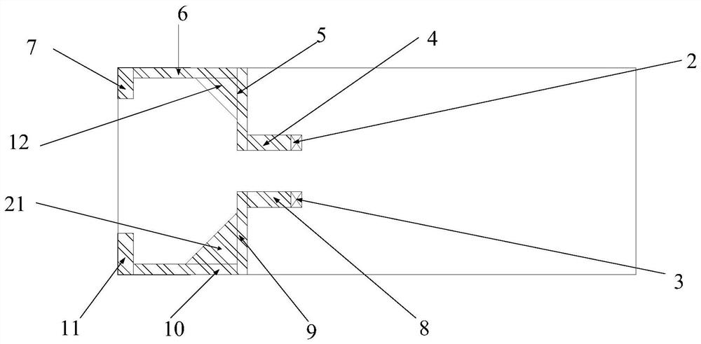
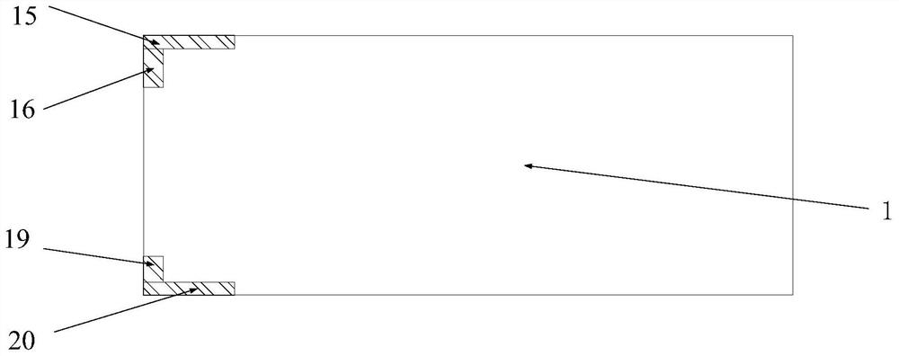
[0019] Example: such as Figure 1-Figure 7 As shown, a miniaturized mobile terminal antenna supporting dual-mode coexistence includes a dielectric substrate 1, a first feed network 2, a second feed network 3, a first antenna radiation unit and a second antenna radiation unit, and a dielectric substrate 1 It is a rectangular plate; the first antenna radiation unit consists of a first rectangular metal conductor 4, a second rectangular metal conductor 5, a third rectangular metal conductor 6, a fourth rectangular metal conductor 7, a fifth rectangular metal conductor 8, and a sixth rectangular metal conductor 9. The seventh rectangular metal conductor 10, the eighth rectangular metal conductor 11 and the first isosceles right triangle metal conductor 12 are composed of the first rectangular metal conductor 4, the second rectangular metal conductor 5, the third rectangular metal conductor 6, the fourth The rectangular metal conductor 7 and the first isosceles right-angled triangl...


PUM

PropertyMeasurementUnit
Lengthaaaaaaaaaa
Lengthaaaaaaaaaa
Heightaaaaaaaaaa

Abstract

The invention discloses a miniaturized mobile terminal antenna supporting dual-mode coexistence. The antenna comprises a dielectric substrate, a first feed network, a second feed network, a first antenna radiation unit and a second antenna radiation unit, and is characterized in that the first antenna radiation unit is positioned on the front side of the second antenna radiation unit; the first radiation unit and the second radiation unit are respectively composed of a plurality of metal conductors, and the metal conductors are sequentially connected and distributed on different surfaces of the dielectric substrate, so that the overall size of the antenna is reduced, and the space utilization rate of the dielectric substrate and the space utilization rate of the mobile terminal are improved; a stepped impedance structure is formed in the first antenna radiation unit and the second antenna radiation unit to achieve broadband and multiband characteristics of the antenna, a fixed decoupling network is used for reducing coupling between the first antenna radiation unit and the second antenna radiation unit, and most of metal conductors are in the same plane, so batch production can be realized by adopting a common PCB processing technology; and the antenna has the advantages of low profile and wide coverage frequency band.

Description

technical field [0001] The invention relates to a mobile terminal antenna, in particular to a miniaturized mobile terminal antenna supporting dual-mode coexistence. Background technique [0002] With the development of wireless communication technology, mobile terminals need to widely support 4G, 5G, Wi-Fi and other communication protocols and meet the increasing traffic demand. In the context of the fact that 5G is not yet widely used today, it is of great significance to configure mobile terminals to support dual-mode (such as 4G and 5G) simultaneous operation and realize carrier aggregation technology (Carrier Aggregation), thereby improving the transmission signal bandwidth. [0003] In order to effectively improve the potential of wireless communication capacity and spectrum utilization required by mobile terminals, multiple-input multiple-output (MIMO) multiple-antenna technology is widely used as a key technical means. Integrating more antenna units into a mobile ter...

Claims


Application Information

Patent Timeline
IPC IPC(8): H01Q1/24H01Q1/36H01Q1/38
CPCH01Q1/36H01Q1/38H01Q1/24
Inventor 陈益华昌洲陆云龙徐俊黄季甫
Owner NINGBO UNIV
Learn More