Air conditioning system for vehicle

A vehicle air conditioner and vehicle technology, which is applied to vehicle components, air handling equipment, heating/cooling equipment, etc., can solve the problems that the amount of air sucked into the condenser cannot be increased, and the stamping pressure cannot be effectively used, etc., to increase the coefficient of performance , reduce the longitudinal size, reduce the effect of load power

Inactive Publication Date: 2006-06-21
DENSO CORP
View PDF0 Cites 4 Cited by
  • Summary
  • Abstract
  • Description
  • Claims
  • Application Information

AI Technical Summary

Problems solved by technology

In addition, the air inlet of the condenser is not toward the front of the vehicle, so when the vehicle is running, the generated ram pressure cannot be effectively used, which creates a problem that the amount of air sucked into the condenser cannot be increased

Method used


Image

  • Air conditioning system for vehicle
  • Air conditioning system for vehicle
  • Air conditioning system for vehicle

Examples


Embodiment Construction

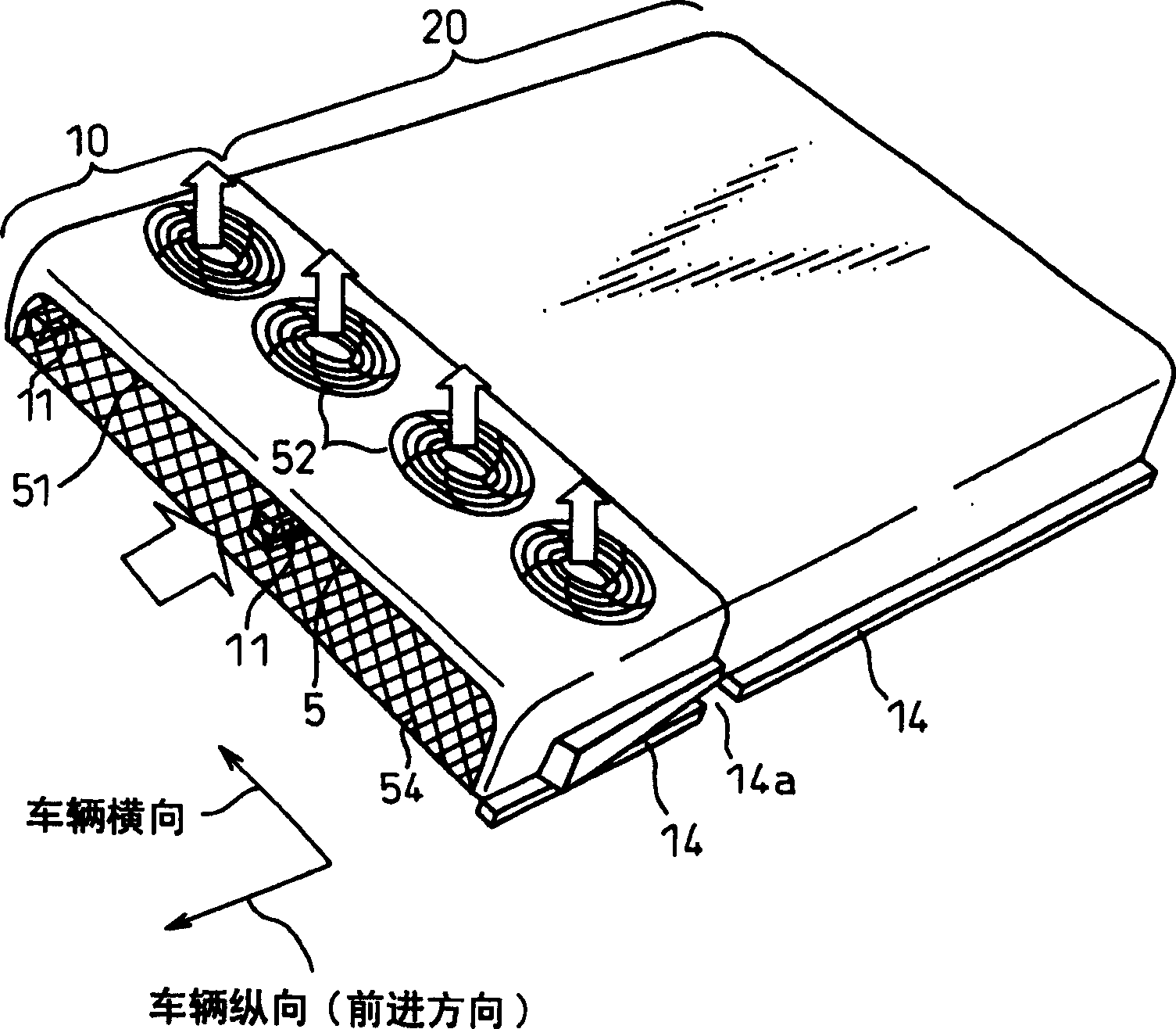
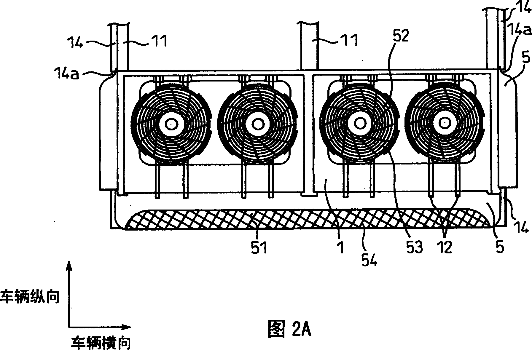
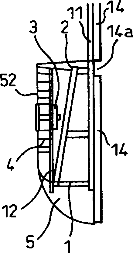
[0029] An air conditioning system for a vehicle according to an embodiment of the present invention will be described below with reference to the drawings. figure 1 is a perspective view illustrating the overall structure of a vehicle air-conditioning system according to an embodiment of the present invention, FIG. 2A is a plan view of a condensing part part, Figure 2B is a side sectional view of the condensing part part, image 3 is a perspective view of the component cover of the condensing component part, Figure 4 is a perspective view of the component housing of the condensing component part.

[0030] The vehicle air conditioning system is placed on a flat roof of a vehicle such as a bus, and is composed of a condensing member section 10 and a cooling member section 20 . A condenser and a condenser fan (which will be described below) are provided inside the condensing part part 10 , and an evaporator and a blower (not shown) are provided inside the cooling part part 2...


PUM


Abstract

In the vehicle air conditioning system according to the present invention, the thin condenser 2 of the condensing part part 10 is installed on the flat roof of the vehicle (such as a bus) and slopes downward from the front to the rear of the vehicle, and the condenser fan 4 is directly arranged Above the condenser, the air inlet 51 of the condenser is arranged in front of the condenser and the air outlet 52 is arranged above the condenser.

Description

technical field [0001] The invention relates to an air conditioning system designed to be mounted on the roof of a vehicle, such as a bus. Background technique [0002] In a traditional air conditioning system designed to be installed on the roof of a vehicle (such as a bus), due to the height limitation of the vehicle, the fan and motor should be placed horizontally on the roof and cannot overlap the condenser vertically. Figure 9 and 10 An example of a traditional layout of an air conditioning system is illustrated. [0003] That is, according to Figure 9 The layout of the condensing part A of the air-conditioning system is shown, in such a way that the air inlet and air outlet are placed horizontally, the cooling fins and the tube condenser C are placed on the surface of the vehicle roof, and the fan and the motor D are placed on both sides of the condenser . Further, the cooling member portion B is placed adjacent to the condensing member portion A in the vehicle lon...

Claims


Application Information

Patent Timeline
Patent Type & Authority Patents(China)
IPC IPC(8): B60H1/32B60H1/00
CPCB60H1/00371B60H1/3227B60H2001/00235B60H1/00
Inventor 米野刚长谷川敦广濑幸裕神谷博
Owner DENSO CORP
Why Eureka
Try Eureka