Multidirection input device

A multi-directional input device and component technology, which is applied to mechanical control devices, input/output processes of data processing, control mechanisms equipped with multiple controlled components, etc. It is not a certain problem, such as discrete pressing force, to achieve smooth tilt and up and down movement, good operation feeling, and small height size.

Inactive Publication Date: 2006-06-28
ALPS ALPINE CO LTD
View PDF0 Cites 0 Cited by
  • Summary
  • Abstract
  • Description
  • Claims
  • Application Information

AI Technical Summary

Problems solved by technology

Therefore, it is difficult to reduce the thickness of conventional multi-directional input devices
[0016] In addition, since the positions where the respective projections 32d, 33d of the first or second interlocking members 32, 33 contact the push-up member 36 deviate from the center, on the push operation shaft 34, the first or second interlocking members 32, 33 When the push-up part 36 is pressed down, the push-up part 36 will be inclined so that the push-up part 36 is guided, so a rough feeling will be produced on the central hole 36c and the guide surface 38a of the b

Method used


Image

  • Multidirection input device
  • Multidirection input device
  • Multidirection input device

Examples


Embodiment Construction

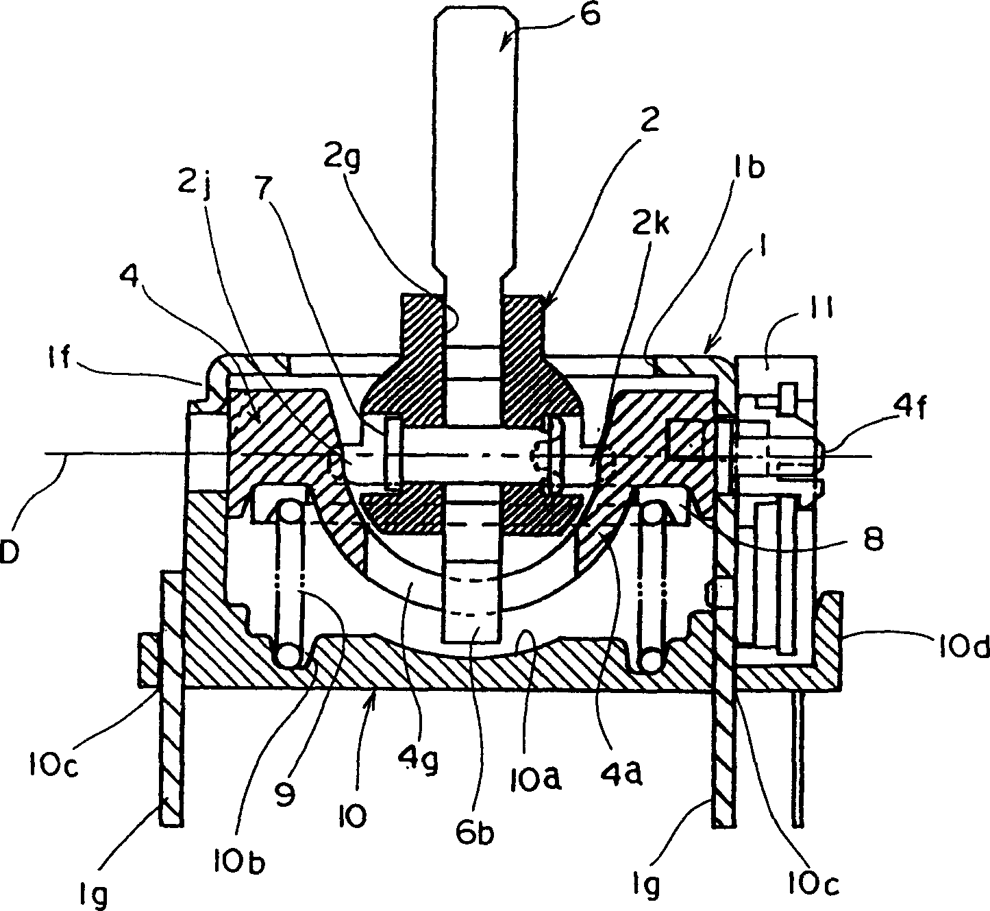
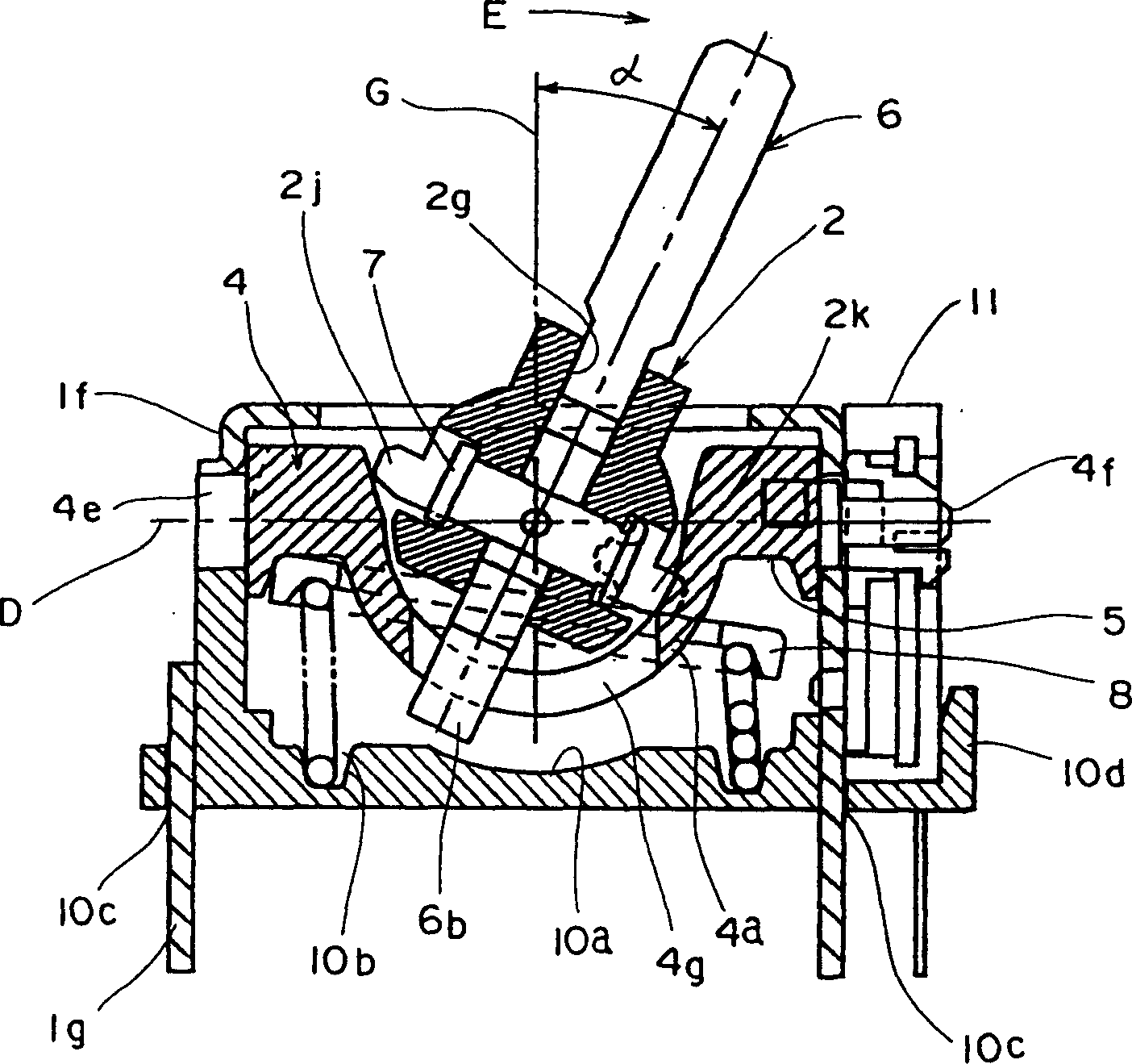
[0077] The multidirectional input device of the present invention such as Figure 5 As shown, the box-shaped housing 1 made of iron plates is bent and formed by stamping and other methods, and the upper part is covered by an upper plate 1a, which is provided with a circular operating hole 1b, and the upper plate 1a The four sides of the shell are provided with side plates 1c, 1d, 1e, and 1f bent downward, and the inside of the shell 1 is a cavity.

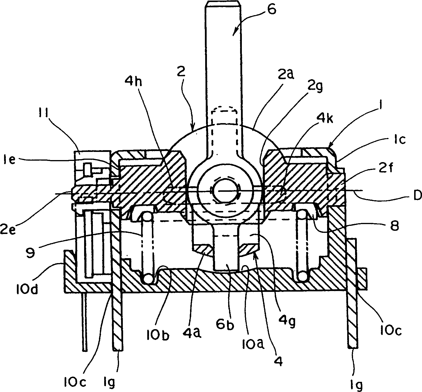
[0078] Inside the cavity of the casing 1, the first and second interlocking components 2, 4 are arranged, perpendicularly intersect each other, and combined into a cross shape.

[0079] Below, refer to Figure 7 ~ Figure 10 The above-mentioned 1st interlocking part 2 is described, and the 1st interlocking part 2 is made of synthetic resin, such as Figure 8 As shown, there is a semicircular base 2a at its center, and one arm 2b protruding to the right as shown in the figure and the other arm 2c protruding to the left as shown in ...


PUM


Abstract

The present invention provides a multidirectional input apparatus capable of making thin form design as well as smooth leaning motion of its operation axis. The solving means is describe in the following. The support parts 2d, 2f, 4d, 4e are respectively mounted at the both ends of the first and the second linking members 2, 4 to support the linking members 2, 4 in the frame 1. The second linking member 4 has a linking part 4a that has a second slot 4g formed between the support parts 4d and 4e. The linking part 4a connects across the lower portion of the first linking member 2 to dispose the first linking member 2 so as to allow the linking part 4a to locate inside the coiled spring 9.

Description

technical field [0001] The present invention relates to a multi-directional input device capable of simultaneously operating a plurality of electrical components by operating an operating shaft. Background technique [0002] Previous multi-directional input devices, such as Figure 20 As shown, there is a box-shaped case 31, and a hole 31b is formed in the center of the upper plate 31a of the case 31. As shown in FIG. Inside the casing 31, the first and second interlocking members 32, 33 are mutually supported rotatably in the vertical direction. [0003] The first interlocking member 32 has a substantially U-shaped connecting portion 32a, and a first elongated hole 32b is formed in the longitudinal direction of the connecting portion 32a. At the lower portion of one end portion of the connecting portion 32a, a locking claw 32c parallel to the longitudinal direction of the connecting portion 32a is protrudingly formed. In addition, protrusions 32d, 32d are protrudingly for...

Claims


Application Information

Patent Timeline
IPC IPC(8): G05G9/047H01C10/20G06F3/033H01C10/16H01C10/32
CPCG05G9/04796H01C10/32G05G2009/04748G05G2009/04777H01C10/16Y10T74/20201
Inventor 石川新治
Owner ALPS ALPINE CO LTD
Why Eureka
Try Eureka