
Ink jet printer head and ink jet printer having said ink jet printer head

A technology of inkjet head and nozzle, applied in the direction of printing, inking device, etc.

Inactive Publication Date: 2006-08-09
BROTHER KOGYO KK
View PDF1 Cites 0 Cited by
  • Summary
  • Abstract
  • Description
  • Claims
  • Application Information

AI Technical Summary

Problems solved by technology

However, the current state of the inkjet head described above cannot fully satisfy such requirements.

Method used


Image

  • Ink jet printer head and ink jet printer having said ink jet printer head
  • Ink jet printer head and ink jet printer having said ink jet printer head
  • Ink jet printer head and ink jet printer having said ink jet printer head

Examples


Embodiment Construction

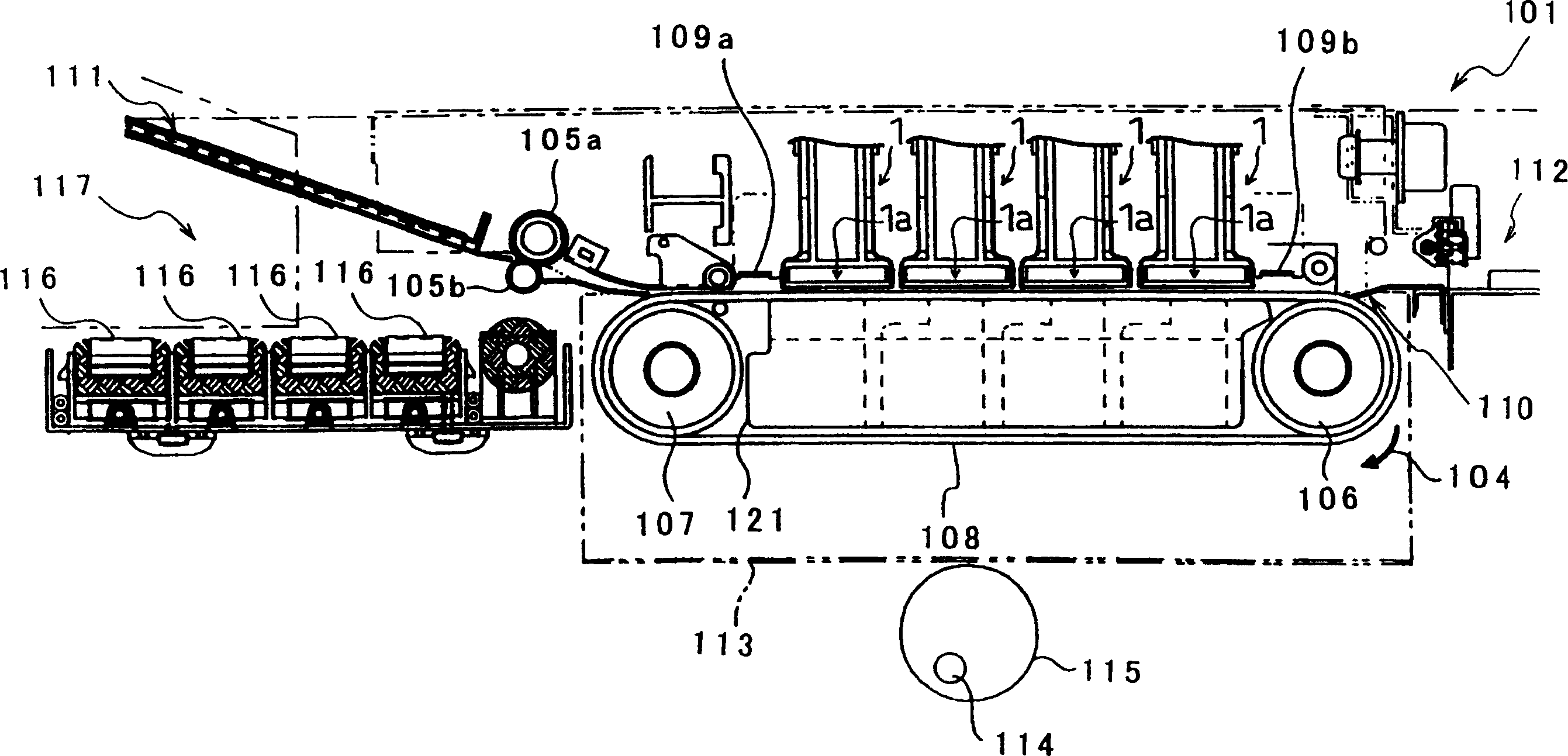
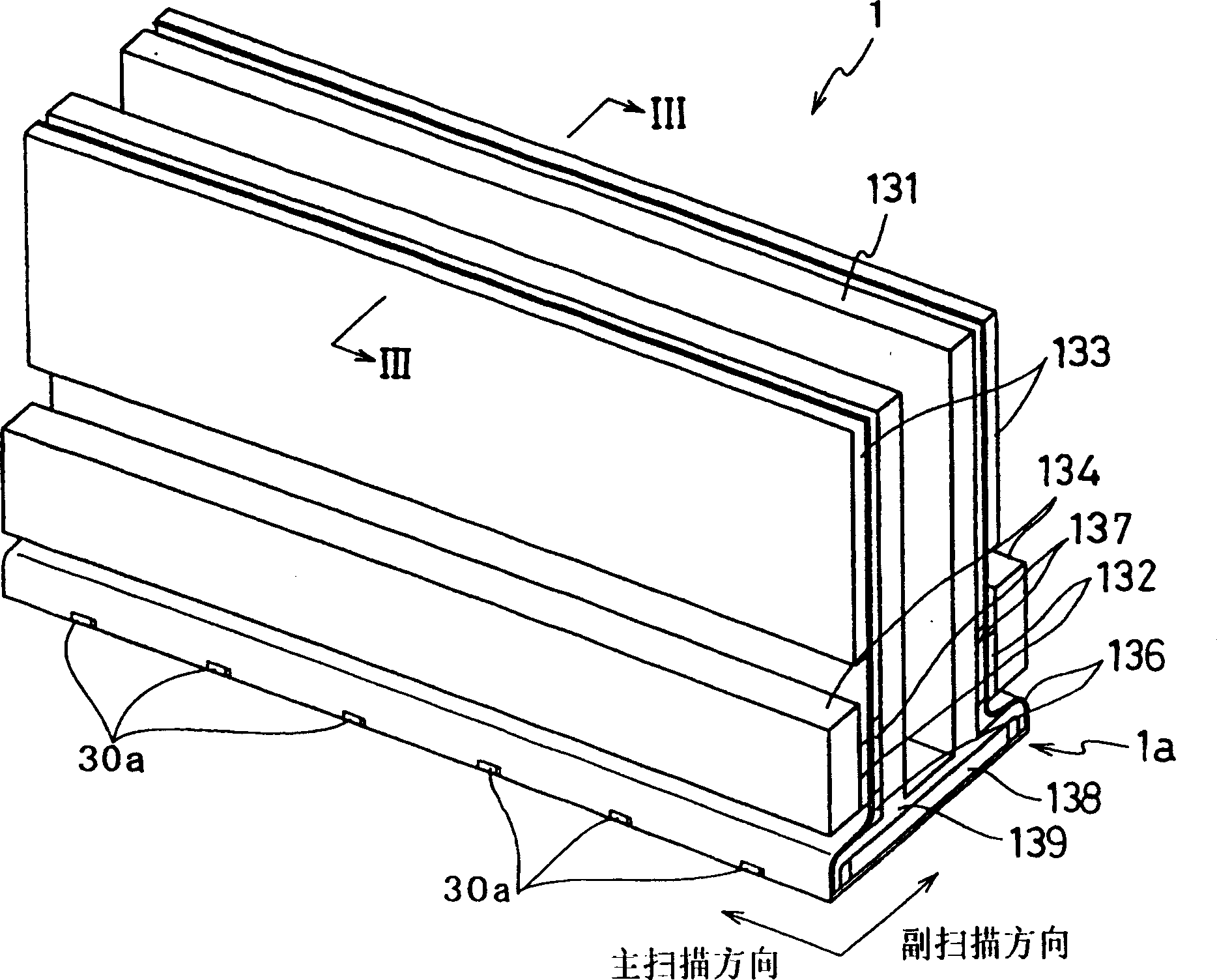
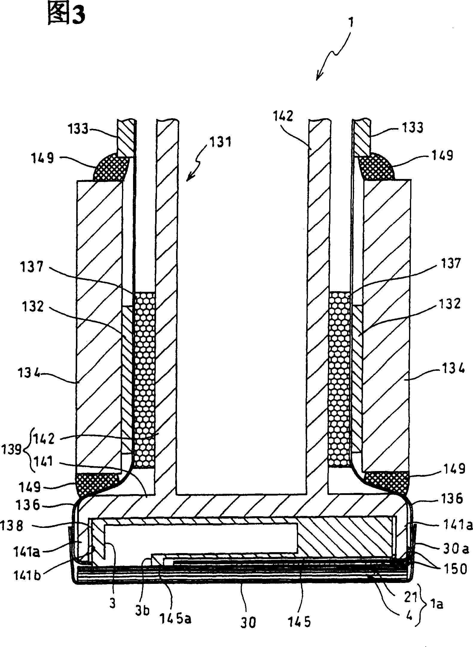
[0025] figure 1 It is a schematic diagram of an inkjet printer including the inkjet head according to the first embodiment of the present invention. figure 1 The illustrated inkjet printer, that is, an inkjet recording device 101 , is a color inkjet printer having four inkjet heads 1 . In this printer 101 , a paper feed mechanism 111 is formed on the left in the figure, and a paper discharge mechanism 112 is formed on the right in the figure.

[0026] Inside the printer 101 , a paper transport path that flows from the paper feed mechanism 111 to the paper discharge mechanism 112 is formed. On the immediately downstream side of the paper feeding mechanism 111, a pair of paper feeding rollers 105a, 105b that sandwich and convey paper as an image recording medium are arranged. The paper is conveyed from left to right in the figure by a pair of paper feed rollers 105a, 105b. In the middle of the paper conveying path, two pulleys 106, 107 are disposed, and an endless conveying b...


PUM


Abstract

An ink-jet head comprises a passage unit including pressure chambers having one end connected with a nozzle and the other end to be connected with an ink supply source, and an actuator unit fixed to a surface of the passage unit for changing the volume of each pressure chamber. The actuator unit is disposed to extend over the pressure chambers. In the passage unit, the pressure chambers are arranged along a plane to neighbor each other, and one nozzle communicates with two or more pressure chambers.

Description

technical field [0001] The present invention relates to an ink-jet head which ejects ink onto a printing carrier to print, and an ink-jet printer having the ink-jet head. Background technique [0002] In an inkjet printer, an inkjet head distributes ink supplied from an ink tank to a plurality of pressure chambers, and selectively applies pressure to each pressure chamber to eject ink from nozzles. As a means for selectively applying pressure to the pressure chamber, an actuator unit is used, which laminates a plurality of piezoelectric plates made of ceramics. [0003] An example of the well-known inkjet head described above has an actuator unit in which a plurality of continuous flat piezoelectric plates spanning a plurality of pressure chambers are stacked, and at least one piezoelectric plate is pressed by a plurality of pressure chambers. The chambers are shared, and the execution unit is sandwiched between the common electrode (common electrode) that maintains the gro...

Claims


Application Information

Patent Timeline
Patent Type & Authority Patents(China)
IPC IPC(8): B41J2/135B41J2/14
CPCB41J2/14209B41J2002/14225B41J2002/14306B41J2002/14459B41J2202/11B41J2202/20
Inventor 坂井田惇夫
Owner BROTHER KOGYO KK
Learn More