Micro-mechanical electrostatic actuator
An electrostatic actuator, micro-machine technology, applied in the direction of electrostatic motor, generator/motor, electrostatic generator/motor, etc., can solve the problems of separating movable electrode 12, difficult sacrificial layer corrosion, difficult structural design, etc., Achieve the effect of lowering the voltage, reducing the occupied area, and increasing the driving force
- Summary
- Abstract
- Description
- Claims
- Application Information
AI Technical Summary
Problems solved by technology
Method used
Image
Examples
no. 1 approach
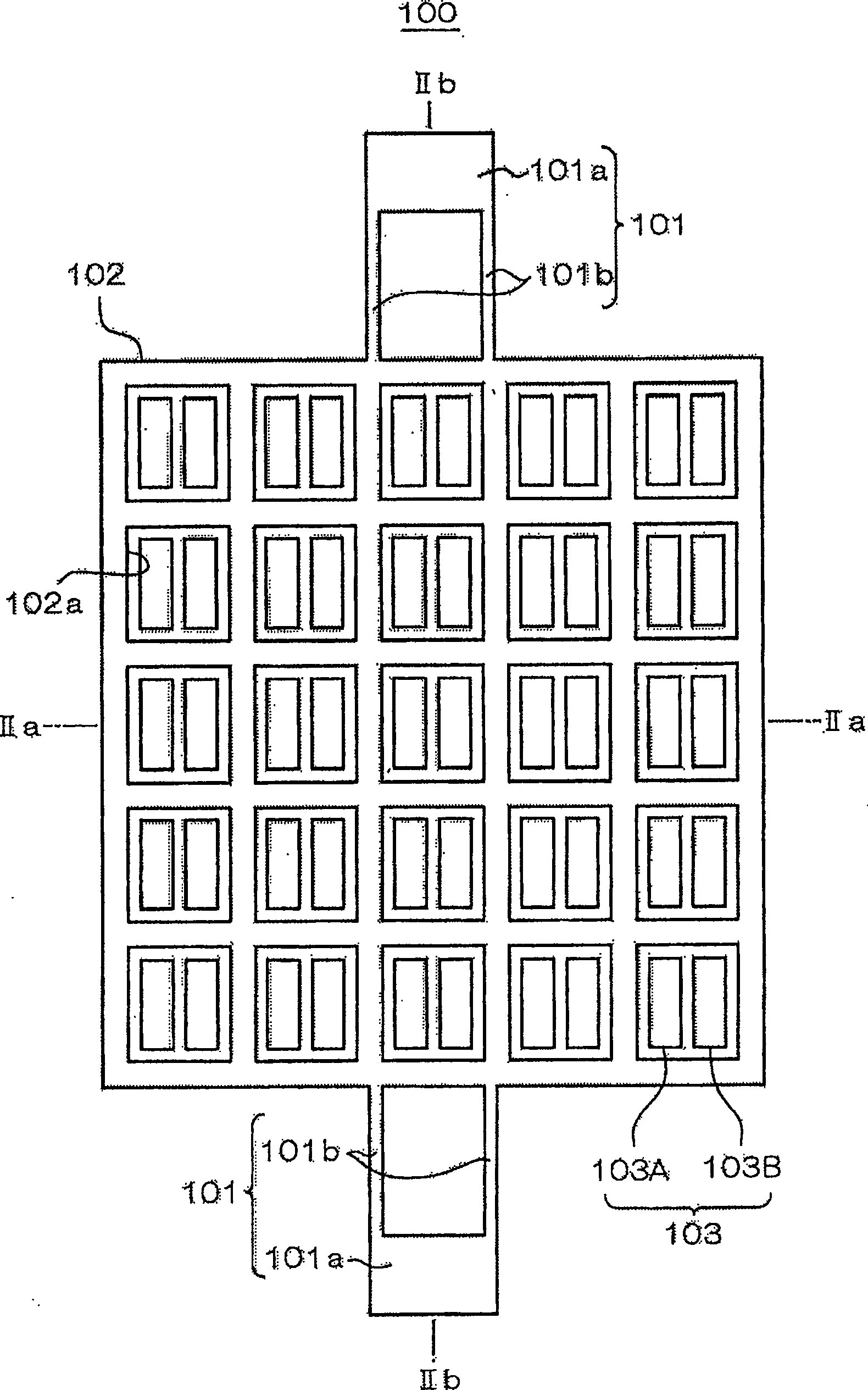
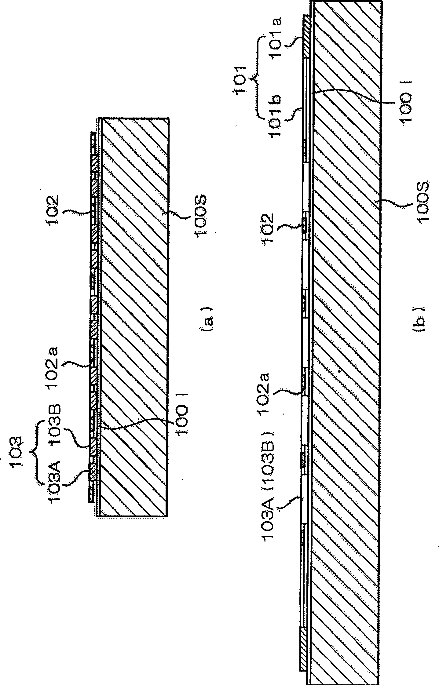
[0048] figure 1 It is a top view showing the planar structure of the micromechanical electrostatic actuator 100 according to the first embodiment of the present invention; figure 2 (a) is a schematic representation along figure 1 Longitudinal sectional view of the section structure of IIa-IIa line; figure 2 (b) is schematically indicated along the figure 1 Longitudinal sectional view of the sectional structure of line IIb-IIb. This electrostatic actuator 100 has a support body 101, a movable electrode 102, and a drive electrode 103, and is formed by a thin film forming process. figure 2 Formed on the substrate 100S shown in. For example, an insulating layer 100I is formed on a silicon substrate as the substrate 100S, and the above-mentioned support in a thin film form is formed on the insulating layer 100I using a semiconductor having a certain carrier concentration such as polysilicon or a metal such as aluminum. 101 , a movable electrode 102 and a driving electrod...
no. 2 approach
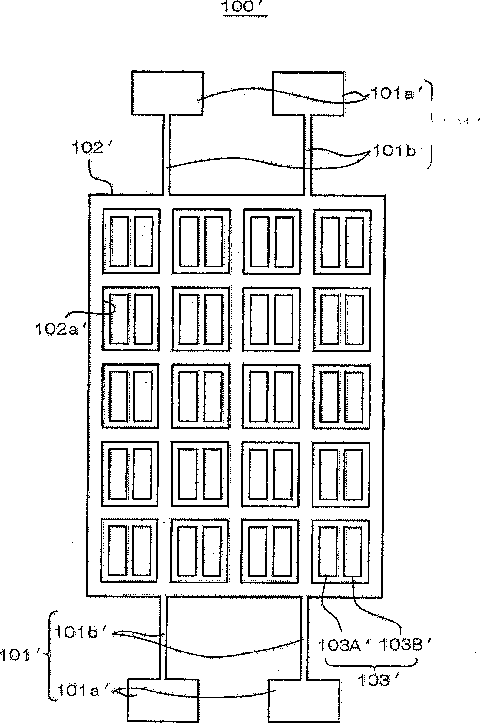
[0058] Second, refer to image 3 A micromechanical electrostatic actuator 100' according to a second embodiment of the present invention will be described. This embodiment has a support 101', a movable electrode 102', and a drive electrode 103' formed on the same substrate as in the first embodiment described above. Here, the movable electrode 102' and the drive electrode 103' are basically the same as those in the first embodiment, and the plurality of openings 102a' are arranged vertically and horizontally in a matrix on the movable electrode 102', and are uniform across the entire movable electrode 102'. distributed configuration. In addition, in the opening portion 102a', a plurality of independent driving electrodes, that is, a first driving electrode 103A' and a second driving electrode 103B' are formed.
[0059] In this embodiment, the support body 101' is the same as that of the first embodiment in that the fixed portion 101a' and the support beam portion 101b' are p...
no. 3 approach
[0062] Below, refer to Figure 6 A micromachine electrostatic actuator 200 according to a third embodiment of the present invention will be described. In this electrostatic actuator 200 , a support body 201 , a movable electrode 202 , and a drive electrode 203 are formed on the same underlying surface as in the first embodiment described above. The support body 201 is provided with the same fixed portion 201a and support beam portion 201b as those of the first embodiment. In addition, both ends of the movable electrode 202 are supported by the pair of supports 201, which is the same as the first embodiment.
[0063] As in the first embodiment, the movable electrode 202 is provided with an opening 202a. In addition, the movable electrode 202 is configured in a state away from the bottom surface, and can move in the planar direction (left-right direction in the figure), which is also the same as the first embodiment. However, only one opening 202a is formed in the movable ele...
PUM
 Abstract
Description
Claims
Application Information
 - R&D
- Intellectual Property
- Life Sciences
- Materials
- Tech Scout
- Unparalleled Data Quality
- Higher Quality Content
- 60% Fewer Hallucinations
Browse by: Latest US Patents, China's latest patents, Technical Efficacy Thesaurus, Application Domain, Technology Topic, Popular Technical Reports.
© 2025 PatSnap. All rights reserved.Legal|Privacy policy|Modern Slavery Act Transparency Statement|Sitemap|About US| Contact US: help@patsnap.com


