Organic electroluminescence device, conductive laminate and display
An electroluminescent element, an organic technology, applied in the direction of electrical components, electric solid devices, circuits, etc., can solve the problems of organic EL element degradation, short circuit, etc., to prevent degradation or short circuit, reduce voltage rise, and achieve long life Effect
- Summary
- Abstract
- Description
- Claims
- Application Information
AI Technical Summary
Problems solved by technology
Method used
Image
Examples
Embodiment approach 1
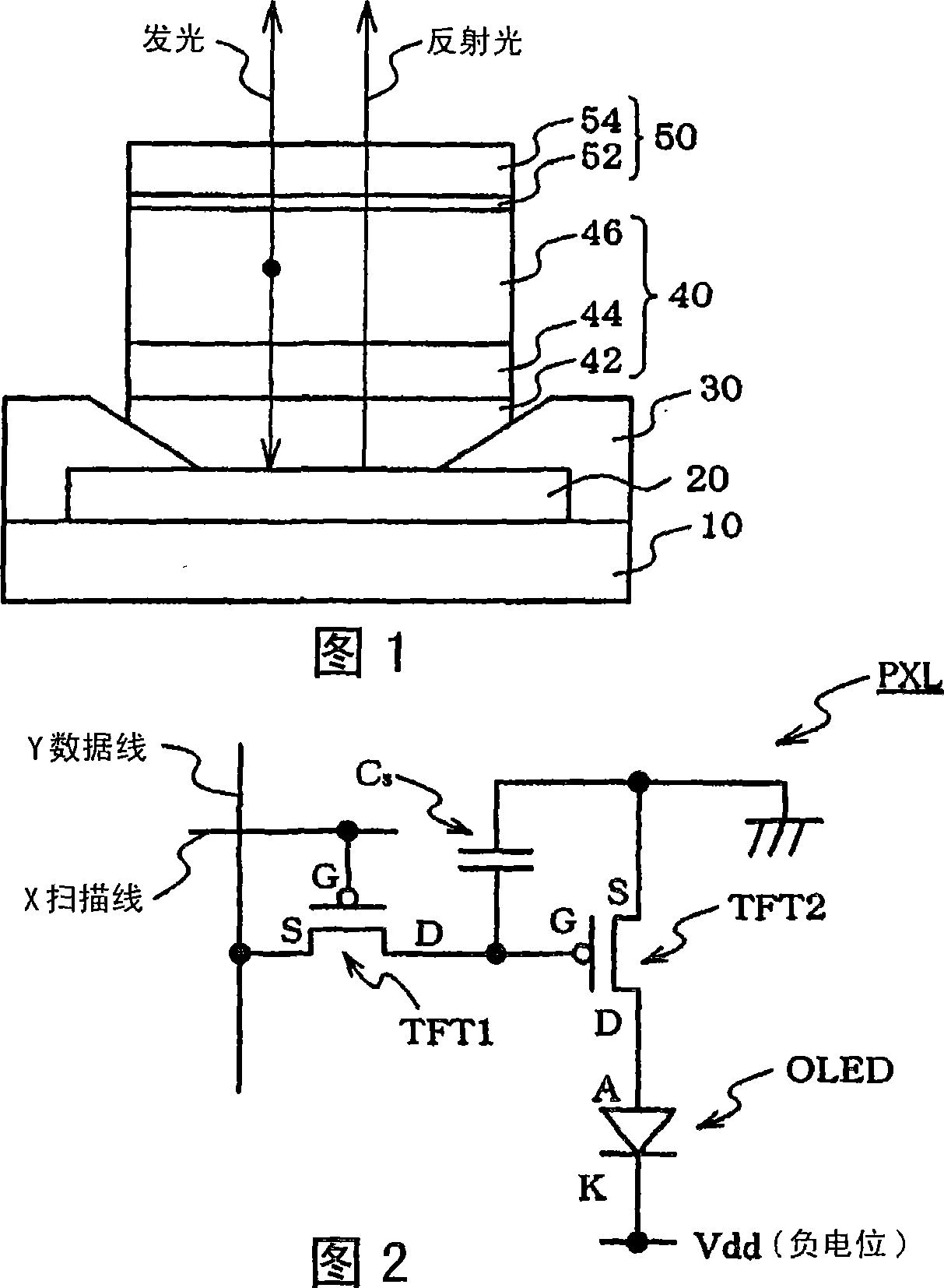
[0056] FIG. 1 is a diagram showing one embodiment of the organic EL element of the present invention. An anode 20, an insulating layer 30, a luminescent layer 40, and a cathode 50 are formed on the substrate. The luminescent layer 40 is composed of a hole injection layer 42, a hole transport layer 44, and a luminescent medium layer 46. The cathode 50 is composed of a metal layer 22, a transparent conductive layer 24 poses. The insulating layer 30 is not an essential layer, but it is preferably provided in order to prevent a short circuit between the anode 20 and the cathode 50 .
[0057] In the light-emitting medium layer 46, the holes provided by the anode 20 and the electrons provided by the cathode recombine to emit light. This luminescence is extracted from above via the cathode 50 .
[0058] In this embodiment, at least one element selected from lanthanum, cerium, neodymium, samarium, and europium is contained in the portion of the anode 40 that is in contact with the h...
Embodiment approach 2
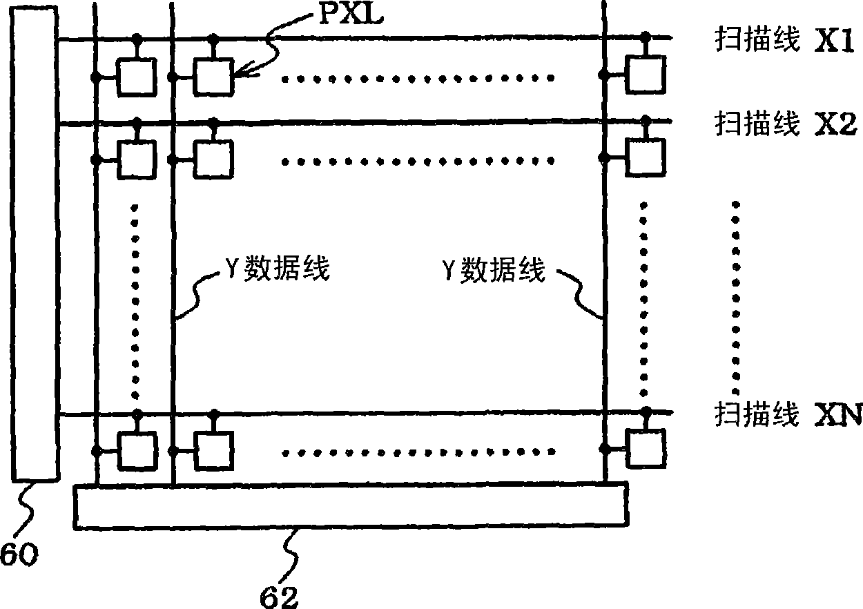
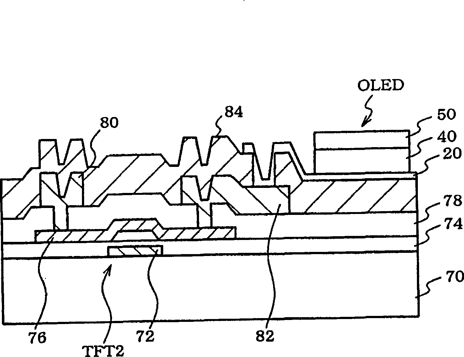
[0064] 2, 3, and 4 are diagrams showing one embodiment of a display device using the organic EL element of the present invention.
[0065] FIG. 2 is a diagram showing an equivalent circuit of one pixel portion of an active matrix display device.
[0066] In an active matrix display device, a plurality of pixels are arranged in a matrix, and the light intensity of each pixel is controlled according to supplied luminance information to display an image. The active matrix method is to control the current flowing in the organic EL element provided on each pixel by an active element (usually a thin-film transistor (TFT) which is a type of insulated gate field effect transistor) provided inside the pixel. .
[0067] The pixel PXL is composed of an organic EL element OLED, a thin film transistor TFT1 as a first active element, a thin film transistor TFT2 as a second active element, and a storage capacitor Cs. Organic EL elements have rectification properties in most cases, so they ...
Embodiment approach 3
[0076] Figure 5 It is a figure which shows one Embodiment of the organic EL element of this invention.
[0077] The organic EL element 134 corresponds to an example of the organic EL element described in the scope of the claims. The organic EL element 134 includes a transparent conductive substrate 138 composed of a glass substrate 110 and a transparent conductive film 112 , a hole transport layer 126 , an organic light emitting layer 128 , an electron injection layer 130 , and a cathode 132 .
[0078]The present embodiment is characterized in that a transparent conductive substrate 138 having a transparent conductive film 112 having a large work function is manufactured. In addition, the present embodiment is also characterized in that, by using such a transparent conductive substrate 138 as an electrode, an organic EL element 134 with a small voltage rise during constant current driving, a long life, and high luminance is manufactured.
[0079] Next, each component and a ...
PUM
| Property | Measurement | Unit |
|---|---|---|
| electron work function | aaaaa | aaaaa |
| thickness | aaaaa | aaaaa |
| thickness | aaaaa | aaaaa |
Abstract
Description
Claims
Application Information
 - R&D
- Intellectual Property
- Life Sciences
- Materials
- Tech Scout
- Unparalleled Data Quality
- Higher Quality Content
- 60% Fewer Hallucinations
Browse by: Latest US Patents, China's latest patents, Technical Efficacy Thesaurus, Application Domain, Technology Topic, Popular Technical Reports.
© 2025 PatSnap. All rights reserved.Legal|Privacy policy|Modern Slavery Act Transparency Statement|Sitemap|About US| Contact US: help@patsnap.com


