Sheet guiding mechanism , sheet conveying device having same and recording device
A technology of a guiding mechanism and a recording device, applied in the directions of printing device, transportation and packaging, thin material handling, etc., can solve the problems of deterioration of operability, inability to use one finger, and high cost.
- Summary
- Abstract
- Description
- Claims
- Application Information
AI Technical Summary
Problems solved by technology
Method used
Image
Examples
no. 1 approach
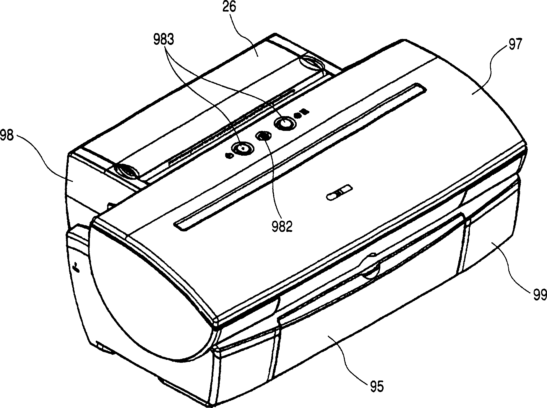
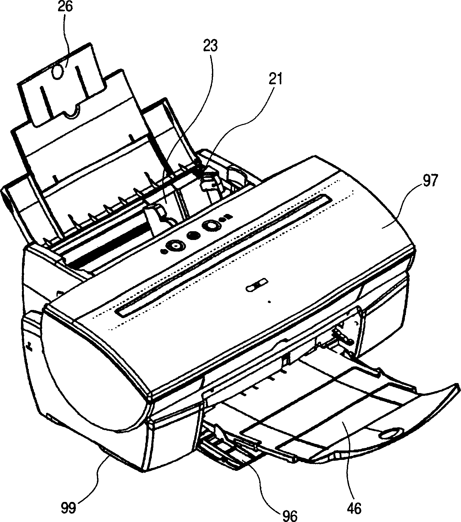
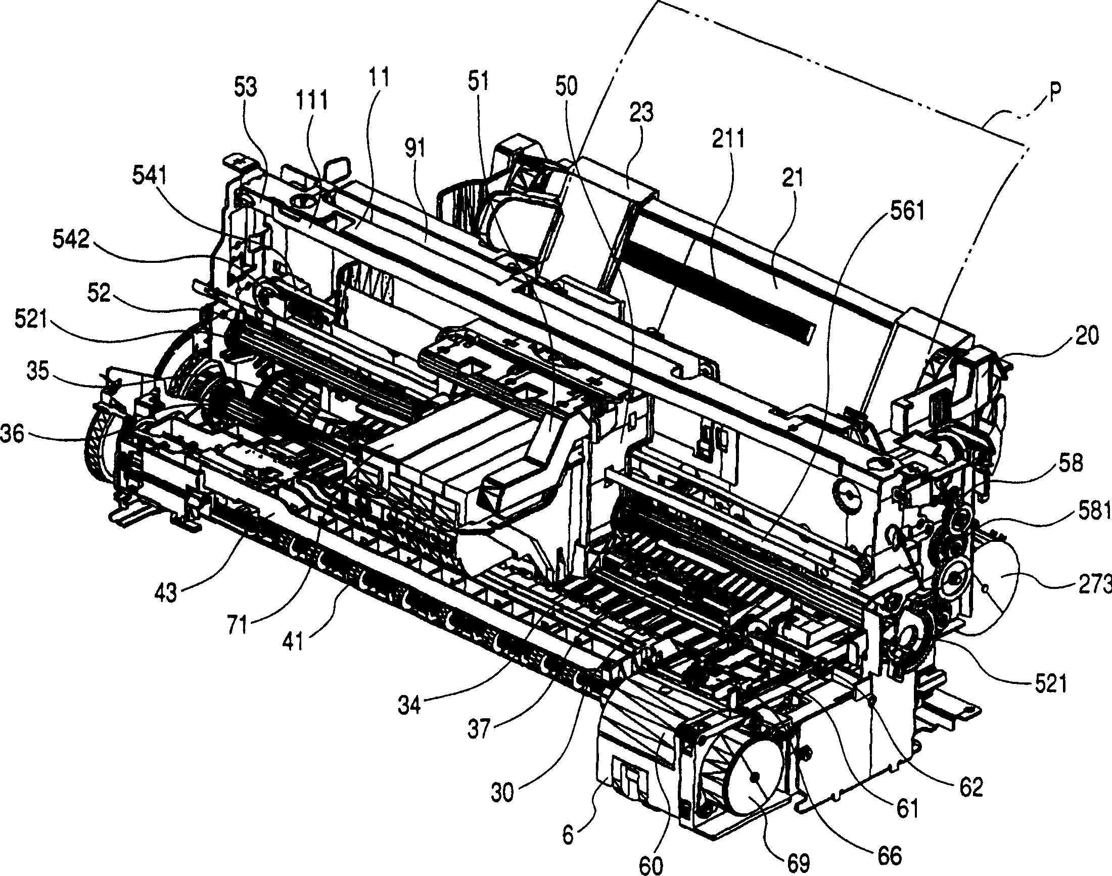
[0029] Below, refer to figure 1 , 2 , 3, 4, 5, 6, 7, 8, 9A, 9B, 9C, 10A, 10B, 11A, 11B, 12A, 12B, and 12C, Embodiment 1 of the present invention will be described. figure 1 and figure 2 is a perspective explanatory view of the recording device of the first embodiment, image 3 and Figure 4 It is a perspective explanatory view of the mechanism part of the recording device of the first embodiment, Figure 5 is a cross-sectional explanatory view of the recording device of the first embodiment, Image 6 , 7 , 8, 9A, 9B, 9C, 10A, 10B, 11A, and 11B are explanatory diagrams related to the sheet feeding device.
[0030] The recording device 1 of the present embodiment is composed of a feeding device 2 , a transport unit 3 , a discharge unit 4 , a carriage unit 5 , a cleaning unit 6 , and the like. Here, they are separated item by item, and their general situation is described in turn.
[0031] (A) Delivery Department
[0032] The feeding section (sheet feeding device) 2 is ...
no. 2 approach
[0090] Below, refer to Figure 12A , 12B and 12C describe the second embodiment. Here, only the parts different from the first embodiment will be described.
[0091] In the first embodiment described above, the movable side guide 23 is formed of resin such as ABS, and the knurl corresponding portion 232 acts on the knurled portion 211 of the pressure plate 21 by virtue of the elasticity of the resin.
[0092] However, as shown in FIGS. 12 , 12B and 12C, it is also feasible to arrange a locking spring (loading mechanism) 238 composed of a compression coil spring or the like between the outer operating portion 233 and the inner operating portion 234 . According to such a configuration, the knurl corresponding portion 232 presses the knurled portion 211 by the urging of the above-mentioned lock spring 238 , and the knurled contact action is performed more reliably. Furthermore, even if the movable side guide 23 and the pressure plate 21 are deformed or the like, the locking fo...
no. 3 approach
[0094] Below, refer to Figure 13 A third embodiment will be described. Here, only the parts different from the first embodiment will be described.
[0095] In the first embodiment described above, the movable side guide 23 is integrally formed of a resin material, however, as Figure 13 As shown, it is also possible to form the parts that make the inner side operation part 234 and the knurled corresponding part 232 into one part, set the center of rotation, and use a locking spring 238 composed of a torsion coil spring to make the knurled corresponding part 232 and the knurled The knurled contact of portion 211.
[0096] According to such a structure, similarly to the second embodiment, the contact function of the knurl corresponding part 232 and the knurling of the knurled part 211 can be made more reliable. Furthermore, even if the movable side guide 23 and the pressure plate 21 are deformed or the like, the locking force will not be lowered. Therefore, the pitch of the...
PUM
 Abstract
Description
Claims
Application Information
 - R&D
- Intellectual Property
- Life Sciences
- Materials
- Tech Scout
- Unparalleled Data Quality
- Higher Quality Content
- 60% Fewer Hallucinations
Browse by: Latest US Patents, China's latest patents, Technical Efficacy Thesaurus, Application Domain, Technology Topic, Popular Technical Reports.
© 2025 PatSnap. All rights reserved.Legal|Privacy policy|Modern Slavery Act Transparency Statement|Sitemap|About US| Contact US: help@patsnap.com


