
turbine rotor

A turbine rotor and rotor shaft technology, applied in turbines, furnace types, electron beam welding equipment, etc., can solve the problems of inability to eliminate the skew of the rotor shaft, reduced productivity of the turbine rotor, high cost, etc., to shorten the production time and improve the finished product. efficiency, low cost

Inactive Publication Date: 2018-06-05
MITSUBISHI HEAVY IND LTD
View PDF2 Cites 0 Cited by
  • Summary
  • Abstract
  • Description
  • Claims
  • Application Information

AI Technical Summary

Problems solved by technology

[0011] As described above, in Patent Document 1, after welding by irradiating electron beams at the junction, tempering is performed by irradiating electron beams while scanning the vicinity of the shaft side of the junction that has become hardened due to the influence of heat. The purpose of the so-called production technology solution of the welding process is not to eliminate the skew of the rotor shaft
[0012] Moreover, as in Patent Document 1, only the tempering of the rotor shaft side area is performed, and the distortion of the rotor shaft cannot be eliminated.
Therefore, if the rotor shaft is skewed after welding, the yield of the turbine rotor decreases
In addition, if the shaft center skew is corrected by machining, two steps of welding and machining are required, which greatly reduces the productivity of the turbine rotor.
[0013] On the other hand, the welding method of Patent Document 2 is considered to be effective in suppressing the residual stress in the circumferential direction, but it requires a plurality of electron beam devices and has a problem of high cost.

Method used


Image

  • turbine rotor
  • turbine rotor
  • turbine rotor

Examples


Embodiment Construction

[0034] Hereinafter, the present invention will be described in detail using the illustrated embodiments. However, the dimensions, materials, shapes, relative arrangements, and the like of the components described in this embodiment are not intended to limit the scope of the invention thereto, unless otherwise specified.

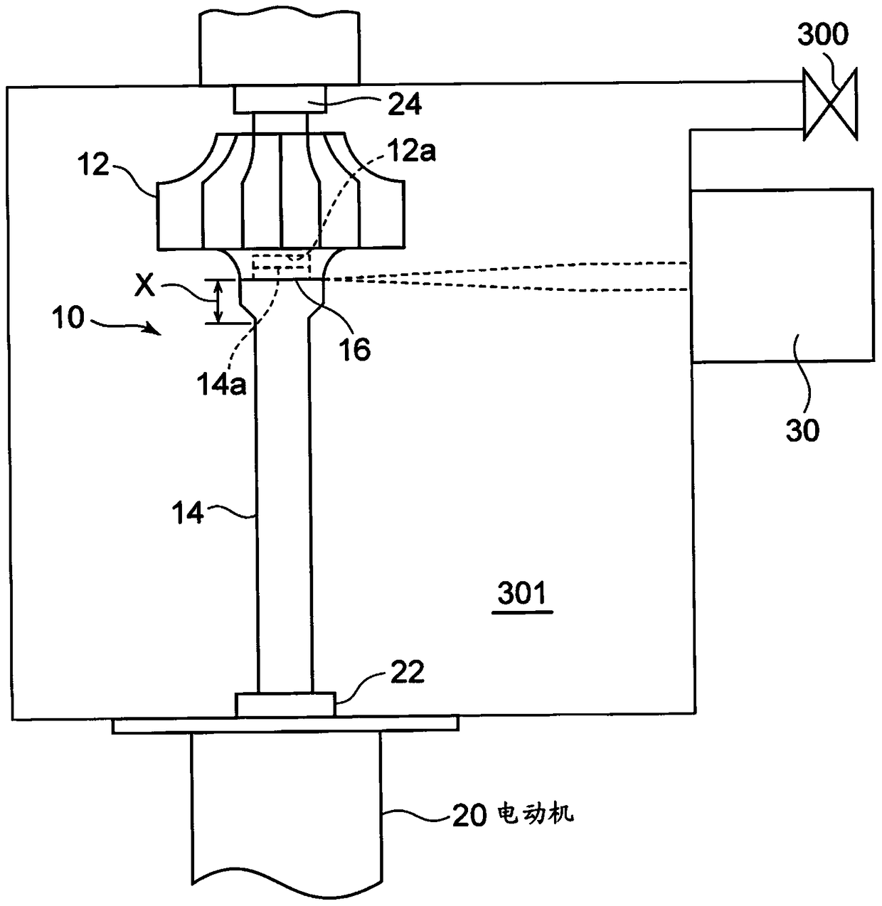
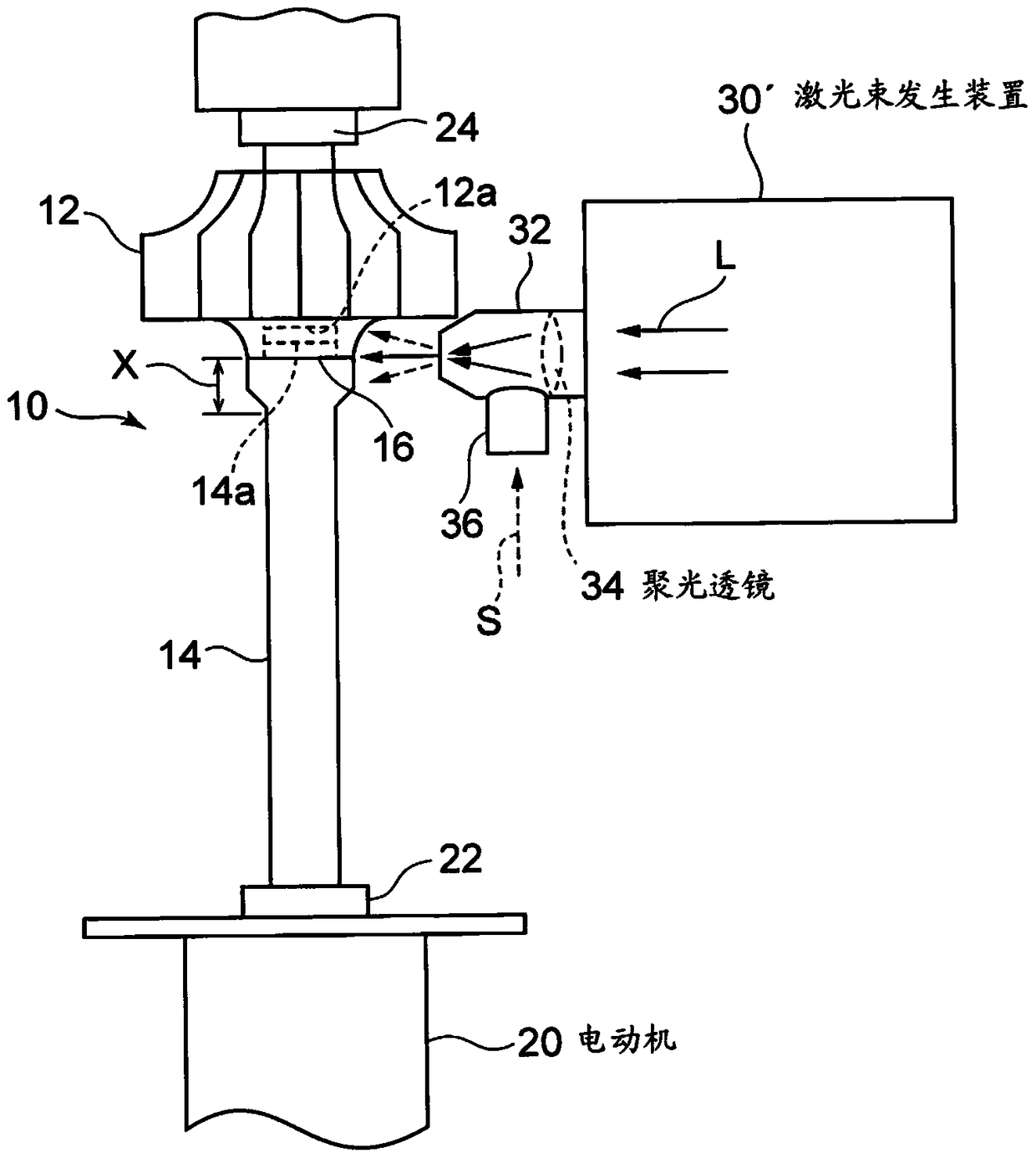
[0035] based on Figure 1A ~ Figure 4 One embodiment of the present invention will be described. Figure 1A A welding device for welding the turbine wheel 12 and the rotor shaft 14 constituting the turbine rotor 10 is shown. The chuck 22 is connected to the output shaft of the motor 20 , and the lower end of the rotor shaft 14 is mounted on the chuck 22 . The rotor shaft 14 is rotated together with the chuck 22 by the motor 20 . A convex portion 14 a smaller in diameter than the rotor shaft 14 is formed at the upper end of the rotor shaft 14 , and a concave portion 12 a fitted to the convex portion 14 a is formed at the center of the lower surface of the t...


PUM


Abstract

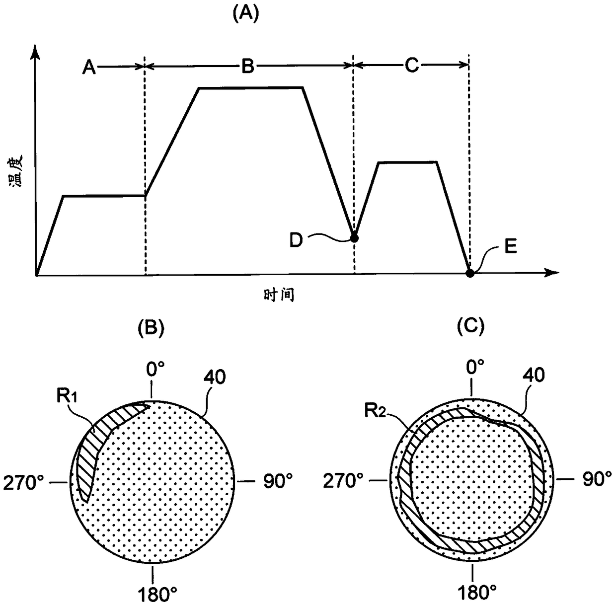
The object of the present invention is to realize a mass-produced turbine rotor that suppresses the skew of the rotor shaft after welding with a low-cost device, improves the yield, and makes the turbine impeller (12) and the rotor shaft (14) align with the concave-convex portion ( 12a, 14a) are rotated while being fitted, and the laser beam L is irradiated on the joint surface (16) in the circumferential direction from the laser beam generator (30) to weld the joint (16). Next, the laser beam L is polarized, and the rotor axis side region X including the welded portion is tempered with the laser beam L. Residual stress R2 is generated over the entire circumference by tempering with respect to the residual stress R1 of the local angular distribution that occurs during welding. Thereby, the distortion of the rotor shaft (14) after cooling is suppressed.

Description

technical field [0001] The present invention relates to a turbine rotor capable of preventing the axial center of the rotor shaft from being skewed during operation by removing residual stress during manufacture and being used, for example, in a turbocharger for automobiles. Background technique [0002] The turbine rotor that constitutes the turbocharger for automobiles requires heat resistance for the turbine impeller, so the turbine impeller made of heat-resistant material and the rotor shaft that does not need to be specially made of heat-resistant material are manufactured using different materials. Soldering etc combine the two. That is, if Figure 5 As shown, in the conventional turbine rotor 100 , the electron beam E is rotated while contacting the joint surface 106 of the turbine wheel 102 and the rotor shaft 104 in a direction perpendicular to the axial direction, and the joint portion 106 is welded over the entire circumference. [0003] In this case, since both ...

Claims


Application Information

Patent Timeline
Patent Type & Authority Patents(China)
IPC IPC(8): F02B39/00B23K15/00B23K15/04B23K26/00B23K26/21B23K31/00C21D9/00C21D9/50B23K26/352
CPCC21D9/50F01D5/063F05D2220/40F05D2230/40B23K15/0006B23K15/0026B23K26/702C21D9/0068C21D1/09C21D1/30B23K2101/001B23K15/0053F05D2240/60F01D5/025F05D2230/234
Inventor 大坪瞳新井贵惠比寿干
Owner MITSUBISHI HEAVY IND LTD
Learn More