
Induction heating device

A technology of an induction heating device and an induction heating coil, applied in the field of induction heating devices, can solve the problems of long setup time, difficult transportation, labor and time consuming of the induction heating device, etc.

Active Publication Date: 2020-06-30
FUJI ELECTRIC CO LTD
View PDF6 Cites 0 Cited by
  • Summary
  • Abstract
  • Description
  • Claims
  • Application Information

AI Technical Summary

Problems solved by technology

And, in the case of using the above-mentioned method to the conventional induction heating device described in Japanese Patent No. 3608240, since the upper part of the yoke portion, the induction heating coil and the furnace frame occupy most of the overall size of the induction heating device ( relatively large), therefore, laborious and time-consuming
Therefore, there is a problem that the setting time of the induction heating device becomes longer
In addition, since the upper part of the relatively large yoke, the induction heating coil, and the steel columns included in the furnace frame need to be transported to the installation site, it may be difficult to transport them beyond the limitations of transport vehicles on roads. question

Method used


Image

  • Induction heating device
  • Induction heating device
  • Induction heating device

Examples


Embodiment Construction

[0031] Hereinafter, an embodiment in which the present invention is embodied will be described based on the drawings.

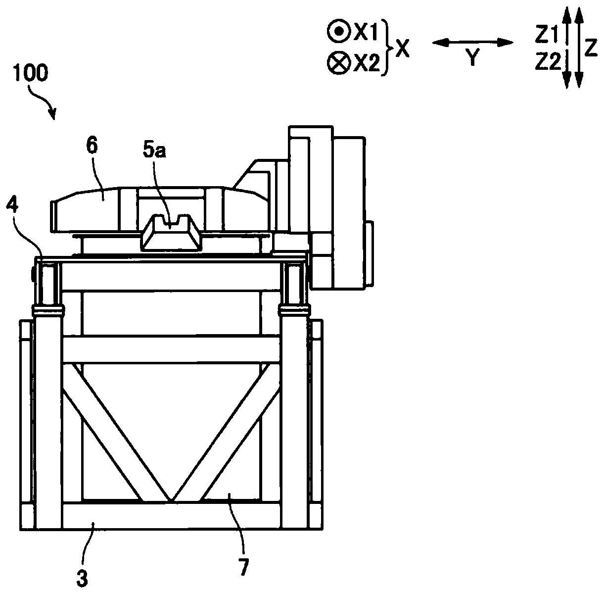
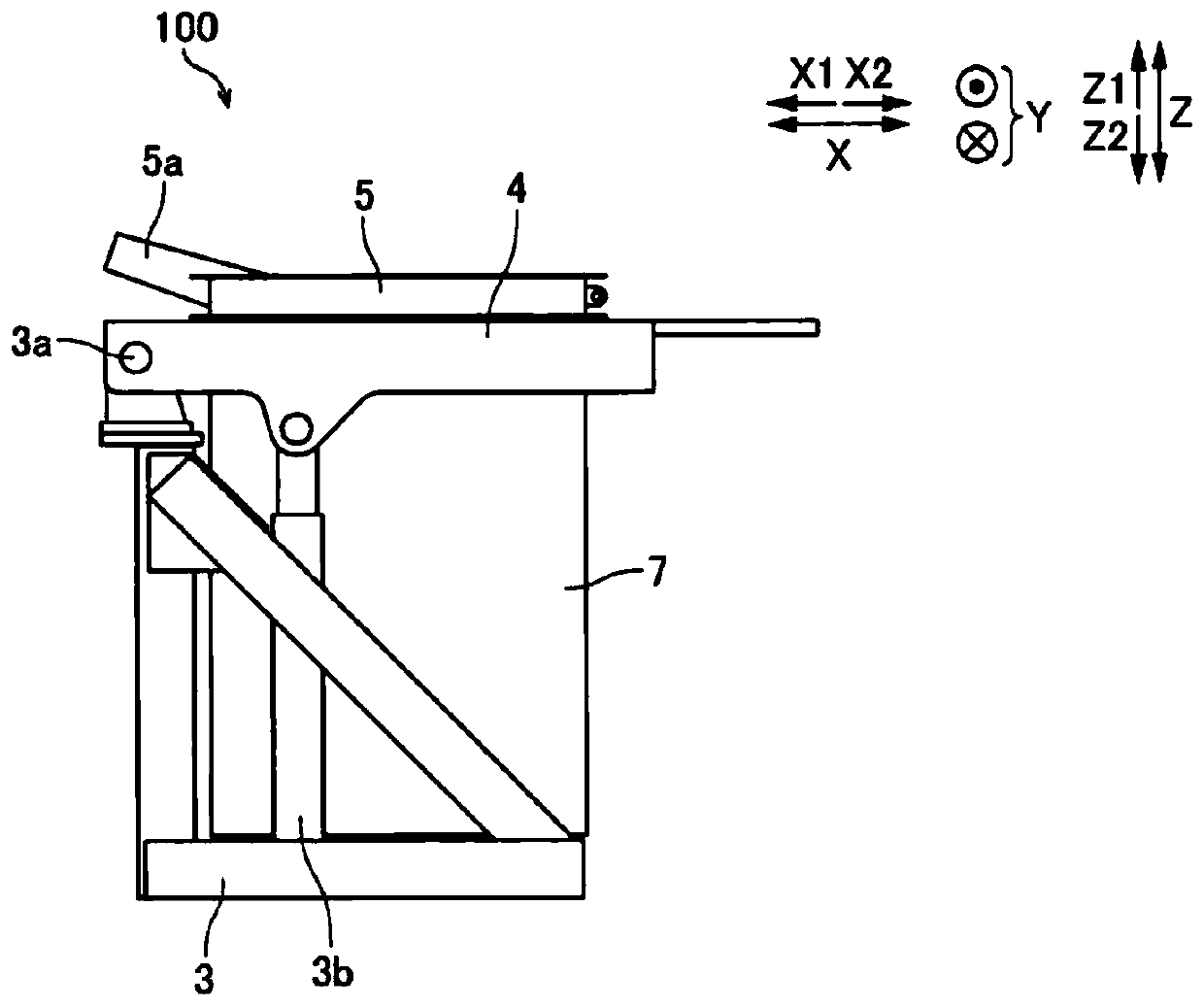
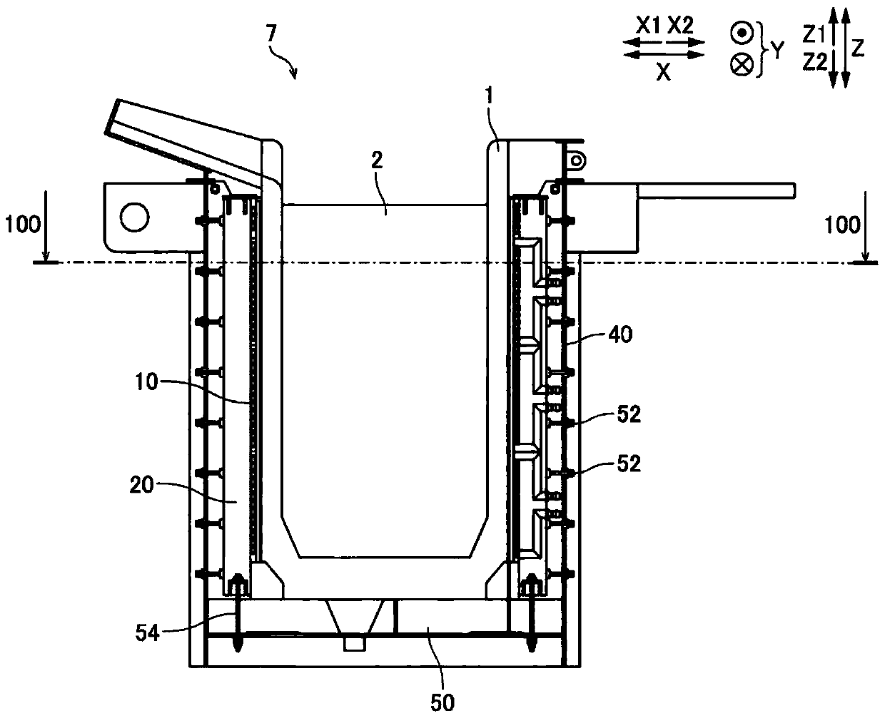
[0032] refer to Figure 1 to Figure 10 The structure of the induction heating apparatus 100 which concerns on one Embodiment of this invention is demonstrated. The induction heating device 100 is used to heat a heat-resistant crucible 1 (refer to image 3 ) of the internal metal material 2 (refer to image 3 ) and a device for melting the metallic material 2 .

[0033] Such as figure 1 As shown, the induction heating device 100 includes a furnace base 3 , a platform 4 , an upper charging machine (Japanese: upper kasta) 5 , a dust collecting hood 6 , a crucible 1 and a furnace body 7 .

[0034] The furnace base 3 supports the furnace body 7 and the table portion 4 . The furnace body 7 and the platform 4 are fixed to each other. Such as figure 2 As shown, the furnace base 3 is connected to the table portion 4 by a rotating shaft 3a. The furnace base 3...


PUM


Abstract

The invention provides an induction heating device. The induction heating device includes: an induction heating coil wound around the outer periphery of a crucible; a yoke disposed along the outer periphery of the induction heating coil; and an oven frame disposed on the outer peripheral side of the yoke, the induction heating coil, the yoke, and the oven frame being configured so as to be capableof being divided into a plurality of parts in the vertical direction in a state of being integrally fixed to one other. By adopting the induction heating device, the transportation can be easily carried out and the setting time can be shortened even under the condition of large scale.

Description

technical field [0001] The invention relates to an induction heating device, in particular to an induction heating device comprising an induction heating coil, a yoke and a furnace frame. Background technique [0002] Conventionally, an induction heating device including an induction heating coil, a yoke, and a furnace frame has been disclosed. For example, Japanese Patent No. 3608240 discloses such an induction heating device. [0003] Japanese Patent No. 3608240 discloses a crucible-type induction melting furnace (induction heating device), which includes a crucible made of a refractory material, an induction coil (induction heating coil) wound around the periphery of the crucible, An L-shaped iron core (yoke portion) arranged along the outer periphery of the induction coil, and a furnace frame including a plurality of steel columns arranged on the outer peripheral side of the L-shaped iron core. In the crucible-type induction melting furnace described in Japanese Patent...

Claims


Application Information

Patent Timeline
Patent Type & Authority Applications(China)
IPC IPC(8): H05B6/36
CPCH05B6/36Y02P10/25
Inventor 松永和久岩丸阳介山本胜也只野英显
Owner FUJI ELECTRIC CO LTD
Learn More