
Powder forming pressing method and powder forming pressing device for green compact for cutting insert

A cutting blade and powder technology, used in material forming presses, presses, manufacturing tools, etc., can solve the problems of skew or deformation of cutting blades, uneven density of raw material powder, etc.

Active Publication Date: 2022-03-15
MITSUBISHI MATERIALS CORP
View PDF10 Cites 0 Cited by
  • Summary
  • Abstract
  • Description
  • Claims
  • Application Information

AI Technical Summary

Problems solved by technology

[0006] And, as described above, if the die, the upper punch having the lower end surface of the shape of the upper surface of the green compact for cutting inserts plane-symmetrically reversed, and the upper punch having the lower surface of the green compacts for cutting inserts plane-symmetrically reversed If the lower punch of the upper end surface of the shape is used to powder-form the compact for cutting inserts, the density of the raw material powder for the compact for cutting inserts will become denser at the thinner portion between the upper and lower surfaces of the compact for cutting inserts. , and become sparse in the thick part, resulting in uneven density of the raw material powder
Therefore, when such a green compact for a cutting insert is sintered, as a result, the cutting insert is skewed or deformed due to the uneven density of the raw material powder.

Method used


Image

  • Powder forming pressing method and powder forming pressing device for green compact for cutting insert
  • Powder forming pressing method and powder forming pressing device for green compact for cutting insert
  • Powder forming pressing method and powder forming pressing device for green compact for cutting insert

Examples


no. 1 approach

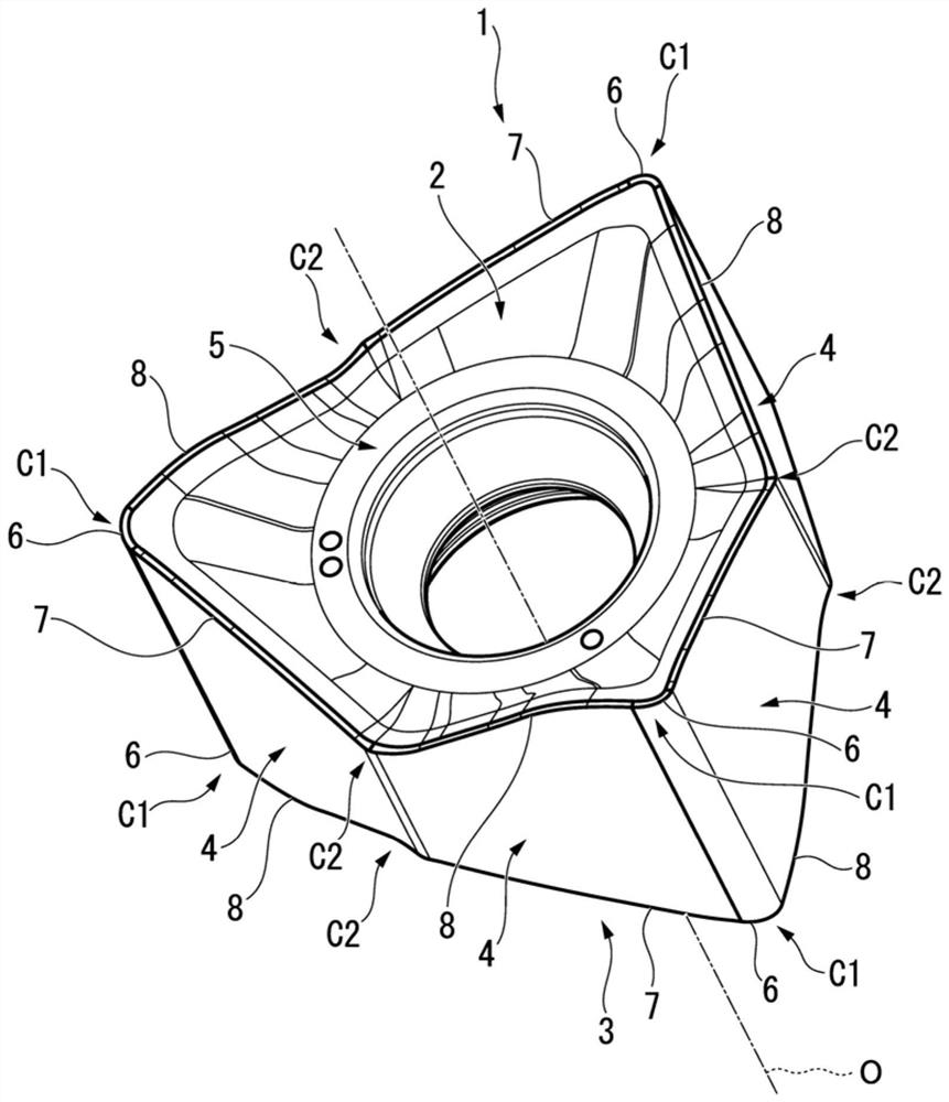
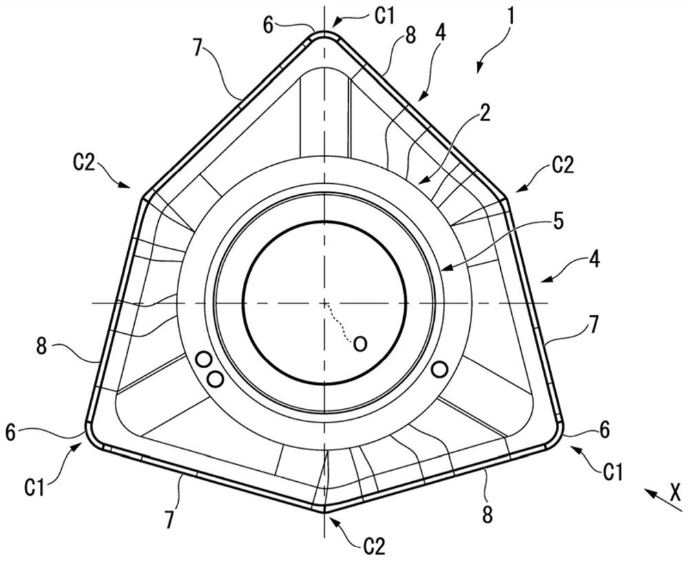
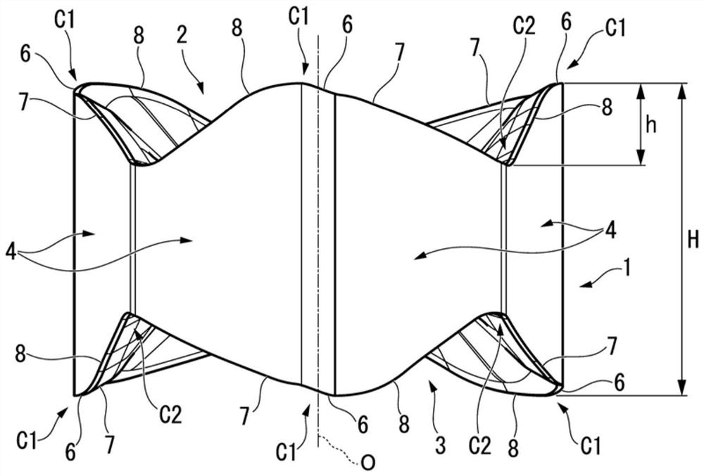
[0109] Figure 1 to Figure 3 Shown is a cutting insert produced by sintering a green compact for a cutting insert obtained by powder compacting and pressing according to the first or second embodiment of the powder compacting method for a green compact for a cutting insert and the powder compacting apparatus of the present invention. Figure 4 to Figure 13 A powder compacting apparatus for a compact for a cutting insert according to an embodiment is shown. also use the Figure 4 to Figure 13 The powder compacting method of this embodiment will be described.

[0110] Such as figure 1 and figure 2 As shown, the insert body 1 of the cutting insert obtained by sintering the green compact for the cutting insert obtained by powder molding and pressing in this embodiment is formed in a non-uniform hexagonal shape from hard materials such as cemented carbide, cermets, and ceramics. The cutting insert is plate-shaped, and has uneven hexagonal upper and lower surfaces 2, 3 and six si...

no. 2 approach

[0152] As described in the description of the first embodiment, Figure 1 to Figure 3 It shows a cutting insert produced by sintering a green compact for a cutting insert obtained by powder molding and pressing according to the first and second embodiments of the powder compacting method for a green compact for a cutting insert and the powder compacting apparatus according to the present invention. Figure 14 to Figure 23 The powder compacting apparatus for the green compact for cutting inserts of the second embodiment is shown. also use Figure 14 to Figure 23 The powder compacting method of this embodiment will be described.


PUM


Abstract

According to the present invention, in the powder molding and pressing method of a compact for a cutting insert whose thickness in the direction of the insert center line (PO) between the upper surface and the lower surface is partially different, the lower punch (112, 212) is inserted into the In the state in the hole portion (111A, 211A) of the die (111, 212), the raw material powder (R) is filled into the molding space (Q), and the green compact for the cutting blade is reversed to have shape and plane symmetry. The shape of the upper surface is different, for example, the preforming surface (114B, 214B) of the concave and convex surface in the opposite direction is preformed with an upper punch (114, 214) inserted into the forming space (Q) from above for preforming or further reshaping The raw material powder (R) is filled, thereby making more raw material powder (R) than the thinner portion in the insert center line (PO) direction between the upper surface and the lower surface compared to the state before preforming. ) is filled to the thick part, the upper punch for final molding is inserted into the molding space (Q) from above to powder-mold and press the raw material powder (R).

Description

technical field [0001] The invention relates to a powder molding and pressing method and a powder molding and pressing device for a compact for a cutting blade that is sintered into a cutting blade. [0002] This application claims priority based on Patent Application No. 2017-105548 and Patent Application No. 2017-105549 filed in Japan on May 29, 2017, and uses the contents thereof here. Background technique [0003] As such a powder compacting method and a powder compacting apparatus for a green compact for a cutting insert, for example, as described in Patent Document 1, the raw material powder for a green compact for a cutting insert is usually filled into a die, an upper punch, and a lower punch. In the molding space formed by the punch, the raw material powder is compressed by the upper punch and the lower punch for powder molding and pressing. The upper and lower surfaces of the green compact for cutting inserts obtained by powder molding and pressing in this way hav...

Claims


Application Information

Patent Timeline
Patent Type & Authority Patents(China)
IPC IPC(8): B22F3/035B22F7/00B30B11/00
CPCB22F3/03B30B11/00B22F7/00B22F3/004B22F2005/001B30B15/022B22F3/02B22F2003/033B22F7/062B22F2005/005B30B11/007B30B11/04B22F5/00B30B11/02B22F5/10B30B11/027F16C2220/20
Inventor 大野健太郎堀田胜合田知二涩谷祥知
Owner MITSUBISHI MATERIALS CORP
Learn More