
Device for controlling lace-up device on shoes and shoes including the device

一种牵拉装置、操纵装置的技术,应用在鞋缚紧物、鞋类、鞋底等方向,能够解决昂贵、功能不够可靠等问题,达到组件数量少、确保生产和安装的效果

Inactive Publication Date: 2006-10-11
埃貢福斯溫克爾
View PDF1 Cites 18 Cited by
  • Summary
  • Abstract
  • Description
  • Claims
  • Application Information

AI Technical Summary

Problems solved by technology

This known device is expensive and its function is not reliable enough

Method used


Image

  • Device for controlling lace-up device on shoes and shoes including the device
  • Device for controlling lace-up device on shoes and shoes including the device
  • Device for controlling lace-up device on shoes and shoes including the device

Examples


Embodiment Construction

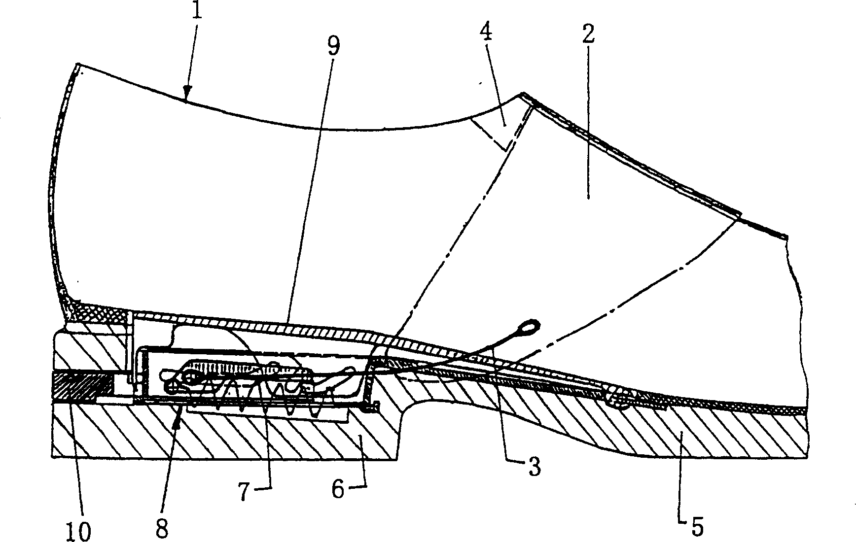
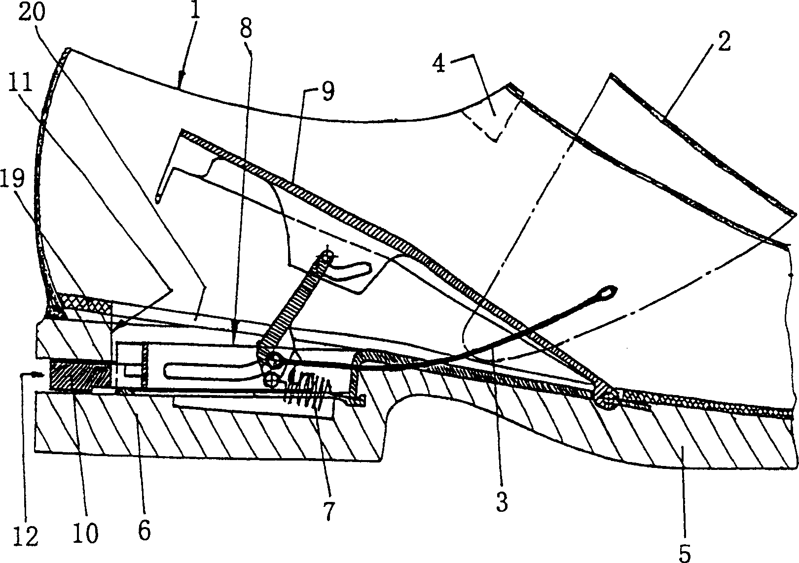
[0030] Such as figure 1 As shown in and 2, the shoe 1 includes a strap 2 which encloses an instep vamp area with an elongated opening. A tightening puller 3 acts on each side end of the strap 2 . These can be strong, crush-resistant plastic straps that can be used as push-pull elements. The tightening puller 3 may have a hook capable of hooking into an eyelet on the strap. Each side of the strap 2 preferably has some holes, so that it is possible to adjust the desired tightness of the entire tightening puller consisting of the strap 2 and the side tightening puller 3 .

[0031] The tightening pull 3 acts on the underside of the strap 2 and is arranged in a corresponding guide groove on the shoe. Therefore, the tightening puller 3 is not visible from the outside. Move the tightening puller 3, so that the strap 2 can be moved from figure 1 The tensioned position in which the shoe remains closed is moved to the loosened position in which the long opening of the shoe 1 shown ...


PUM


Abstract

An operating device for a tightening and pulling device for shoes (1), which consists of a slider (22), a tensioning rod (9) and a rocker (39), and has a simple, clear design and Good safety; the guide member (37) of the sliding member (22) includes two branches (37a, 37b); the sliding member (22) includes a stopping surface (28), and the rocker (39) includes a matching Joint (41) through which the slide (22) can be moved to the rear locking position; the slide (22) includes a guide (30) and the rocker (39) includes a mating joint The rocker (39) is engaged with the guide member (37), and the engaging member (41) can move to a position suitable for entering the front branch (37a) of the guide member (37).

Description

technical field [0001] The invention relates to an operating device for a tightening and pulling device for shoes, which device comprises a housing arranged in the rear area of ​​the sole, a slide with a rearward projection received in said housing The raised part of the shoe so that it can slide along the longitudinal direction of the shoe; the device also includes a tension rod surrounding the seat groove, the tension rod is held at its front end so that it can move up and down, the tension rod The rod can be pressed down by the heel when putting on the shoe; when the tension rod is in its depressed state, it is locked with the slider already in the backward locked position, and the slider can be unlocked by moving forward; The underside of the tensioning rod comprises a guide for the top end region of a rocker, the bottom end region of the rocker acts together with the tensioning pull and is guided in a longitudinal guide, the rocker being guided by A spring device is pre-...

Claims


Application Information

Patent Timeline
Patent Type & Authority Patents(China)
IPC IPC(8): A43B11/00A43C1/00A43C11/00A43C1/06A43B11/02A43B13/14A43B21/42A43B21/45A43C11/16
CPCA43B11/00A43B21/42A43B21/45Y10T24/37
Inventor 埃贡·福斯温克尔
Owner 埃貢福斯溫克爾
Learn More