Front wheel fork structure for saddle type vehicle

A vehicle and saddle type technology, applied in the field of front fork structure, can solve the problems of complex structure and troublesome front fork forming, and achieve the effect of large cross-sectional area

Inactive Publication Date: 2006-11-08
YAMAHA MOTOR CO LTD
View PDF0 Cites 0 Cited by
  • Summary
  • Abstract
  • Description
  • Claims
  • Application Information

AI Technical Summary

Problems solved by technology

Wherein, since the above-mentioned front fork has many components, its structure is more complicated, and the forming of the front fork is troublesome.

Method used


Image

  • Front wheel fork structure for saddle type vehicle
  • Front wheel fork structure for saddle type vehicle
  • Front wheel fork structure for saddle type vehicle

Examples


no. 1 Embodiment approach

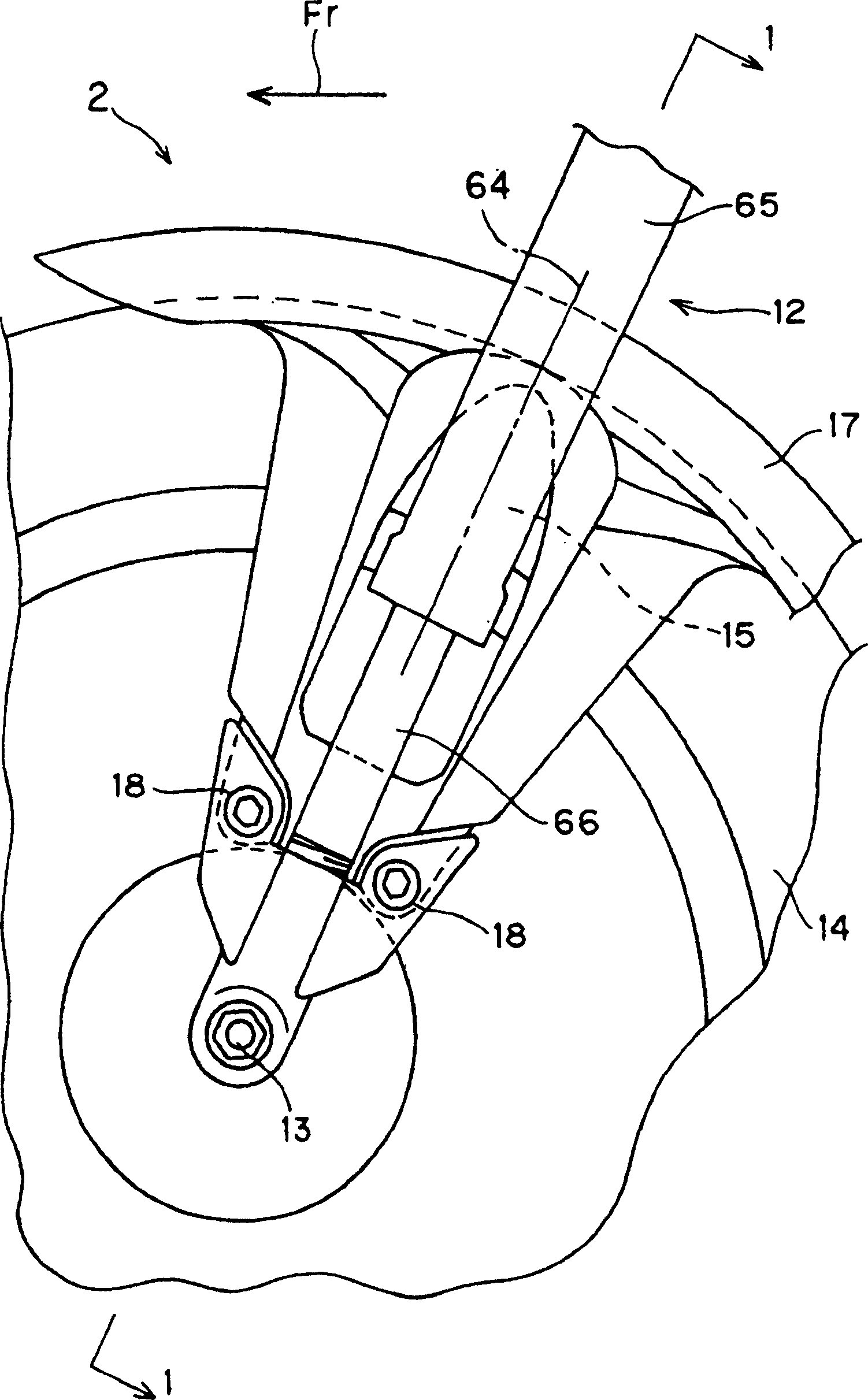
[0019] 1 to 3 show a first embodiment of the present invention.

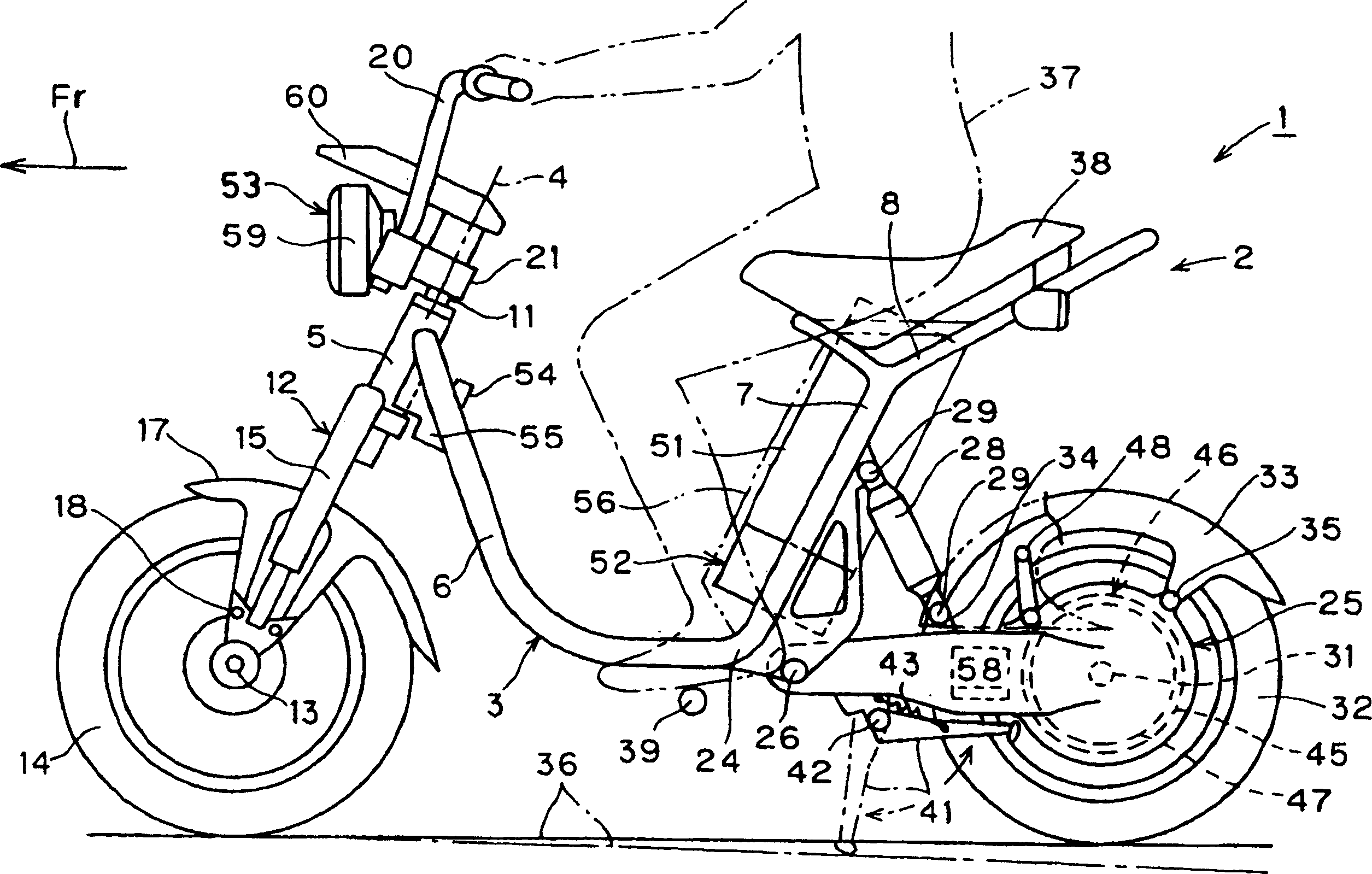
[0020] figure 2 In the figure, reference numeral 1 is a saddle-riding vehicle, and an electric two-wheeled vehicle (motorcycle) is taken as an example to specifically show it. The arrow Fr indicates the front of the vehicle 1, and the so-called left and right referred to below refers to the width direction of the vehicle body 2 of the vehicle 1 facing the above-mentioned front.

[0021] The vehicle body frame 3 of the above-mentioned vehicle body 2 has: a front pipe 5 constituting its front upper end and extending in a downward direction with the axis 4 in the longitudinal direction; 6; a pair of left and right rear struts 7, 7 protruding from the protruding ends of the lower tubes 6, 6 to the rear; an upper frame 8 that combines the protruding ends of these rear struts 7, 7, The vehicle body frame 3 is formed bilaterally symmetrically with respect to an imaginary vertical plane passing through the vehicle bo...

no. 2 Embodiment approach

[0049] Figure 4 The second embodiment of the present invention is shown.

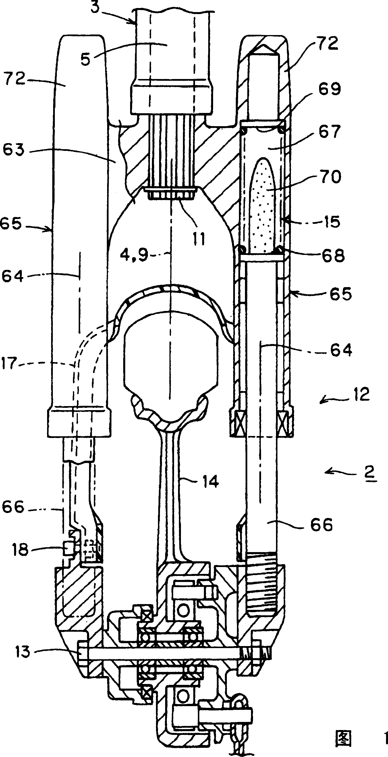
[0050] According to this second embodiment, at least the respective upper portions of the spring 68 and a part of the moving track 74 of the impact limiter 70 are arranged in the space 67 inside the upper end portion 72 of each of the upper pipes 65 .

[0051] Therefore, the upper end portion 72 of each upper tube 65 can be used for disposing the spring 68 and the impact limiter 70, which does not increase the vertical dimension of the front fork 12, and can further improve the shock absorbing function.

[0052] The upper end portion 72 of each of the above-mentioned upper pipes 65 also has: a tubular base portion 72a that is integrally formed with each side portion of the above-mentioned bracket 63 and whose upper end portion protrudes upwards from the upper surface of each side portion of the above-mentioned bracket 63; 72b, a cap 72c detachably attached to the upper end of the base 72a, and the upp...


PUM


Abstract

The present invention aims to simplify the structure of the front fork in which the upper end of the saddle-riding vehicle is supported on the lower end of the steering shaft, to easily form the front fork, and to improve the strength of the front fork. The front fork (12) whose upper end is supported on the lower end of the steering shaft (11) has: a bracket (63) supported on the lower end of the steering shaft (11); 1. A pair of left and right upper tubes (65, 65) protruding in a straight line downward; a pair of left and right lower tubes (66) that can freely slide along the axial direction and fit with the lower end side of each upper tube (65). , 66). The bracket (63) and the left and right upper pipes (65, 65) are integrally formed with each other; the upper end (72) of each upper pipe (65) protrudes upwards than the top of each side portion of the bracket (63).

Description

technical field [0001] The present invention relates to a front fork structure of a saddle-type vehicle. The above-mentioned saddle-type vehicle is provided with a steering shaft supported on a body frame and a front fork whose upper end is supported on the lower end of the steering shaft. Background technique [0002] Conventionally, the front fork structure of the above-mentioned saddle type vehicle has the following structure. [0003] That is, at the front upper end of the body frame provided on the vehicle, the steering shaft is supported freely around the longitudinal axis, and the upper end is supported on the lower end of the steering shaft, and the front fork of the front wheel is supported on the lower end. . [0004] The above-mentioned front fork has: a bracket supported on the lower end of the above-mentioned steering shaft; a pair of left and right upper tubes extending linearly downward from the left and right sides of the bracket; A pair of left and right l...

Claims


Application Information

Patent Timeline
IPC IPC(8): B62K21/02B62K21/18B62K25/08
CPCB62K21/02B62K21/18B62K25/08
Inventor 幸田秀夫
Owner YAMAHA MOTOR CO LTD
Why Eureka
Try Eureka