Multi-cross sectional fluid path condenser

Inactive Publication Date: 2018-08-23
EVAPCO
View PDF4 Cites 0 Cited by
  • Summary
  • Abstract
  • Description
  • Claims
  • Application Information

AI Technical Summary

Benefits of technology

[0005]The present invention ameliorates heat transfer deficiency of the prior art as well as high initial refrigerant pressure drop in the first pass by providing multi-cross sectional fluid paths (circuits) for condensation coupled with segmented headers in lieu of return bends. Thus at the entrance of each circuit when the vapor volume is significant, a larger cross-sectional area is provided for each circuit. The larger total initial cross sectional area reduces the internal pressure drop and the vapor velocity while maintaining the internal film heat transfer coefficient above the external heat transfer coefficient. As the vapor volume decreases along each circuit length as a result of condensation, the total cross sectional area is reduced to maintain a threshold internal film heat transfer coefficient that is equal to or greater than the external heat transfer coefficient. This decrease in total cross sectional area may be accomplished by incorporating a multiple pass circuit selection coupled with a greater total cross sectional area for the initial fluid path in comparison to later passes. This arrangement lowers the initial heat transfer fluid pressure drop per incremental circuit length with minimal heat transfer sacrifice in the first pass. Moreover, it significantly improves the condenser's heat transfer deficiency by increasing the internal film heat transfer coefficient in the later passes in comparison to the prior art single cross-sectional area circuit devices. Overall, the multi-cross sectional condenser of the invention provides greater heat rejection at a lower heat transfer fluid pressure drop. The multi-cross sectional fluid path condenser of the invention can be implemented using larger tubes in the first pass and smaller tubes in subsequent passes, or by using more tubes in the first pass and fewer tubes in subsequent passes, or by some combination of the two, that is reducing both the number of tubes and the cross-sectional area of the tubes in with each subsequent pass.

Problems solved by technology

Moreover, the internal film heat transfer coefficient prior to approaching the exit region of each circuit limits the condenser's potential or overall heat transfer capability.
This in turn limits the refrigerant mass flow rate per tube (or circuit / path).
Conversely, the very low vapor velocity in the last pass adversely affects the internal film heat transfer coefficient and thus reduces the condenser's total heat transfer capability.
Moreover, it significantly improves the condenser's heat transfer deficiency by increasing the internal film heat transfer coefficient in the later passes in comparison to the prior art single cross-sectional area circuit devices.

Method used


Image

  • Multi-cross sectional fluid path condenser
  • Multi-cross sectional fluid path condenser
  • Multi-cross sectional fluid path condenser

Examples


Embodiment Construction

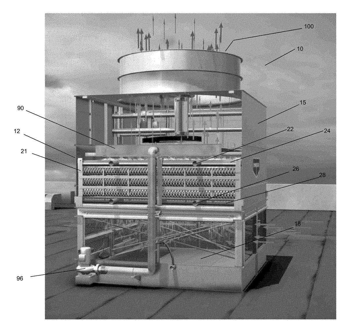
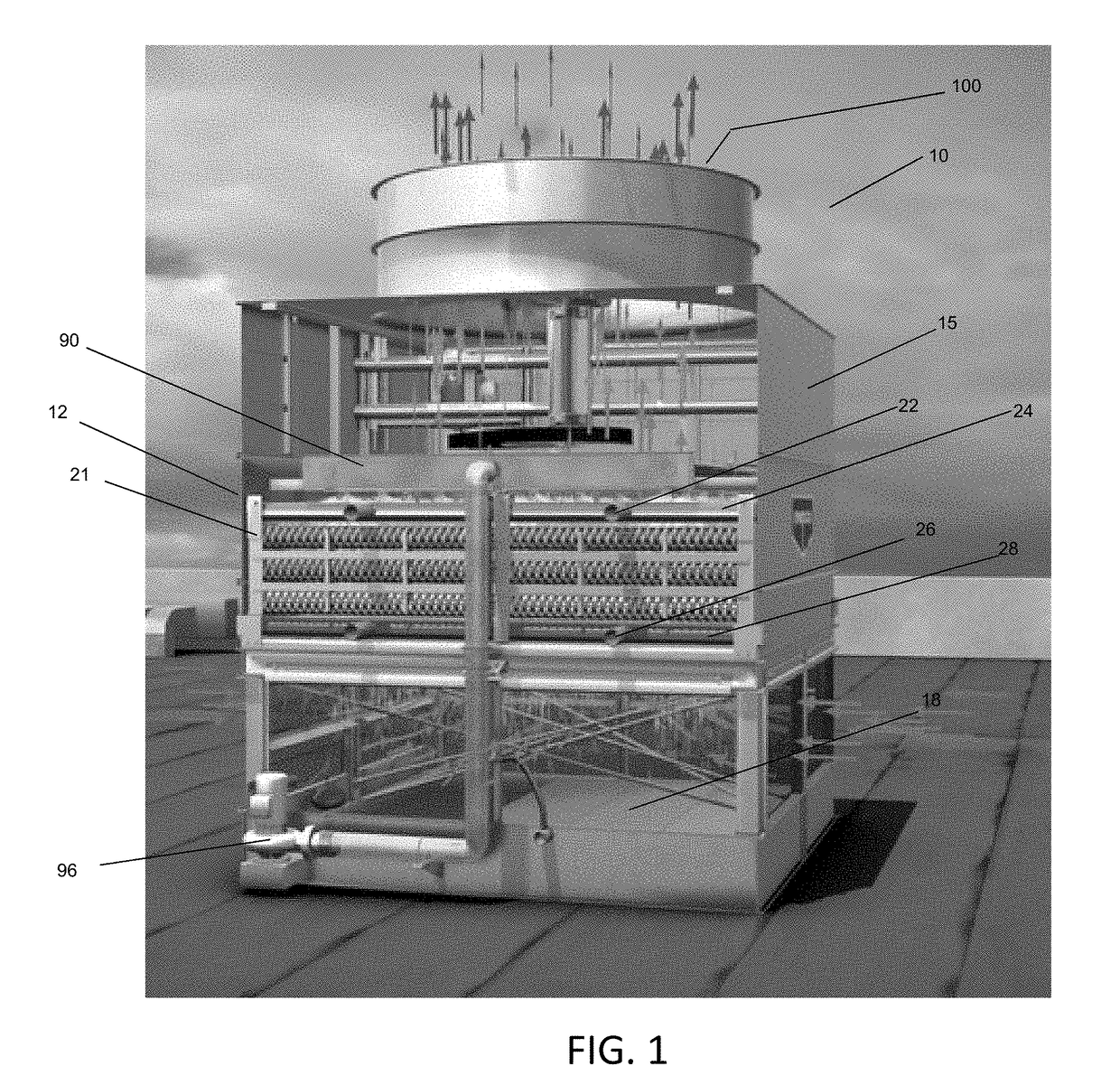
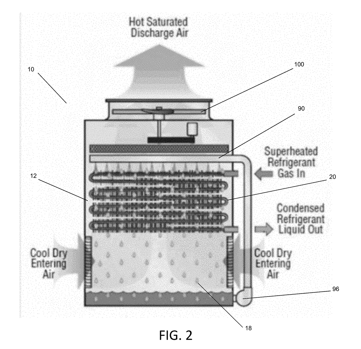
[0019]This invention relates particularly to condenser coil bundles used in refrigerant condensers, and particularly (although not exclusively) in evaporative refrigerant condensers 10 of the type shown in FIGS. 1 and 2 configured to indirectly transfer heat between a superheated refrigerant and ambient air, operative in a wet mode or a dry mode as described below depending on ambient atmospheric conditions, such as temperature, humidity and pressure.

[0020]The apparatus 10 includes a fan 100 for causing air to flow through the apparatus, and as shown schematically in FIG. 1, sitting atop housing 15. At normal ambient atmospheric conditions where freezing of the cooling liquid, typically water, is not of concern, air is drawn into the plenum 18 of the apparatus via air passages at the bottom of the unit through the open air intake dampers, and enters the evaporative heat transfer section 12 where heat transfer takes place involving the distribution of water from a water distribution ...


PUM


Abstract

A refrigerant condenser having multiple sections of straight tubes terminating in segmented headers, each subsequent section having an overall cross-sectional area less than an initial section with the overall cross section of the initial section large enough to substantially reduce vapor velocity thus reducing the refrigerant pressure drop; the total cross-sectional area dimensioned to cause entrance vapor velocity, to be sufficient to establish an internal film heat transfer coefficient greater than the external heat transfer coefficient while limiting the internal pressure drop for the heat rejection intended.

Description

BACKGROUND OF THE INVENTIONFIELD OF THE INVENTION[0001]The present invention relates to refrigeration system air-cooled condensers.DESCRIPTION OF THE BACKGROUND[0002]A typical refrigeration system condenser consists of multiple, serpentine heat transfer fluid paths (or circuits) such that the superheated heat transfer vapor entering each circuit (path) will be condensed completely prior to leaving the heat exchange device. FIG. 3 illustrates an example of a prior art condenser tube bundle. The condenser consists of approximately 50 serpentine tubes, with one inlet header and one outlet header. Vapor enters the upper header (inlet) and is dispersed into all 50 tubes, all having the same diameter. For the entire fluid flow path, the number of the tubes remains constant, and the cross-sectional area of each tube remains constant. At the bottom of the tube bundle, the condensed refrigerant is collected at the outlet header.SUMMARY OF THE INVENTION[0003]The overall heat transfer coeffici...

Claims


Application Information

Patent Timeline
IPC IPC(8): F28F13/08F25B39/04F28D1/047F28D3/04F28F1/02F28F25/02
CPCF28F13/08F25B39/04F28D1/0478F28D3/04F28F1/025F28F25/02F28D2021/007F28F2009/029F28F2025/005F25B2339/041F28C1/14F28D3/02F28F1/325F28D1/0417F28D1/05366Y02B30/70F28B7/00F28D1/053F28F9/02
Inventor STRUDER, GORDON
Owner EVAPCO
Why Eureka
Try Eureka