Method for forming metal plate and apparatus for forming metal plate

Active Publication Date: 2017-01-12
TOYOTA BOSHOKU KK
View PDF11 Cites 1 Cited by
  • Summary
  • Abstract
  • Description
  • Claims
  • Application Information

AI Technical Summary

Benefits of technology

[0006]Particularly, it is preferable for a fuel-cell separator, for example, to have a large cross-sectional area in view of improving the output efficiency of the fuel cell so that gas such as hydrogen and oxygen easily flows through the flow passage.

Problems solved by technology

As a result, a problem arises that the for

Method used


Image

  • Method for forming metal plate and apparatus for forming metal plate
  • Method for forming metal plate and apparatus for forming metal plate
  • Method for forming metal plate and apparatus for forming metal plate

Examples


Example

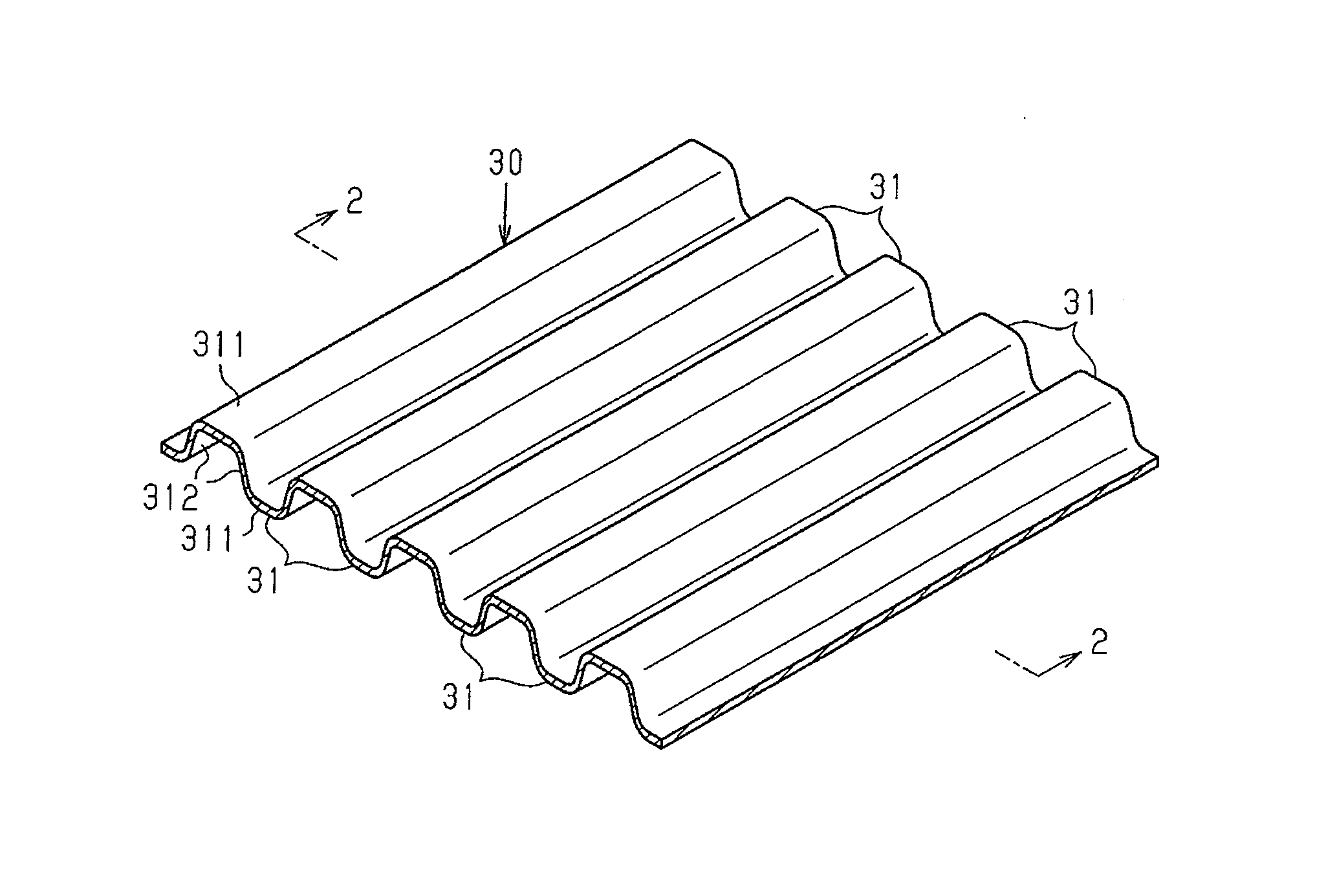
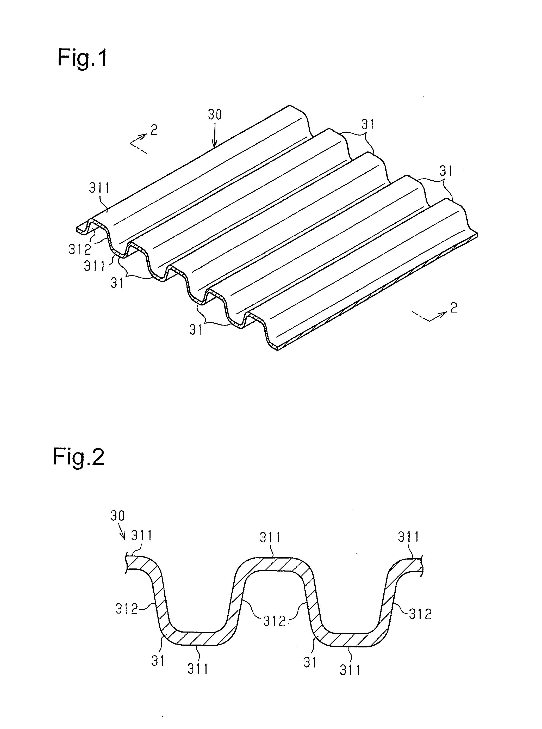
[0022]With reference to FIGS. 1 to 8, one embodiment will now be described. A method and an apparatus for forming a metal plate according to the present embodiment are applied to production of a fuel-cell separator.

[0023]As shown in FIGS. 1 and 2, a metal plate 30, which constitutes a fuel-cell separator, includes bulging portions 31 on the front surface and the back surface (the top surface and the bottom surface in FIG. 2). The bulging portions 31 project toward the front side or the back side so that the metal plate 30 has a pleated shape. The bulging portions 31 are alternately formed on the front surface and on the back surface such that one bulging portion 31 on the back surface side is located between two adjacent bulging portions 31 on the front surface side.

[0024]Each of the bulging portions 31 includes a top 311 that is located at the front end in the projecting direction (the vertical direction of FIG. 2) and two sidewalls 312 that are continuous from the two ends of the ...


PUM

PropertyMeasurementUnit
Shapeaaaaaaaaaa

Abstract

A method for forming bulging portions on a metal plate by performing cold-pressing on the metal plate is provided. The method includes a first step and a second step. In the first step, a pre-formed body including pre-formed bulging portions is formed with a first die. Each pre-formed bulging portion includes sidewalls. Each sidewall includes dents. In the second step, the sidewalls are pressed by a second die so that the dents of the pre-formed body disappear.

Description

BACKGROUND OF THE INVENTION[0001]The present invention relates to a method and an apparatus for forming bulging portions on a metal plate by performing cold-pressing on the metal plate with a die including a die block and a punch.[0002]A conventional fuel-cell separator includes bulging portions provided on a metal plate to form a flow passage through which gas such as hydrogen and oxygen, coolant, or the like flows. For example, Japanese Patent No. 5573511 and Japanese Laid-Open Patent Publication No. 2014-213343 disclose methods for forming a fuel-cell separator.[0003]According to the forming method disclosed in Japanese Patent No. 5573511, as shown in FIG. 9, a die block 41 and a punch 42, which constitute a die 40, press sidewalls 512 of bulging portions 51 of a metal plate 50 while being separated from the tops 511 of the bulging portions 51.[0004]According to the forming method disclosed in Japanese Laid-Open Patent Publication No. 2014-213343, as shown in FIG. 10A, in a first...

Claims


Application Information

Patent Timeline
IPC IPC(8): B21D13/02H01M8/021B21D53/00H01M8/0208
CPCB21D13/02B21D53/00H01M8/021H01M8/0208B21D53/04H01M8/0254Y02E60/50
Inventor HIRATA, KAZUYUKI
Owner TOYOTA BOSHOKU KK
Why Eureka
Try Eureka