
Liquid Discharging Head

Pending Publication Date: 2022-08-11
BROTHER KOGYO KK
View PDF2 Cites 0 Cited by
  • Summary
  • Abstract
  • Description
  • Claims
  • Application Information

AI Technical Summary

Benefits of technology

This patent text describes a liquid discharging head that can prevent air from remaining in the communicating channels between manifolds and minimize the concentration of pressure. By adjusting the cross-sectional area of the communicating channels depending on the number of nozzle rows in both manifolds, the head ensures an appropriate amount of liquid flows and prevents air from accumulating. This results in a more efficient and effective liquid discharging process.

Problems solved by technology

Accordingly, in the above-described configuration, in a case that the channel cross-sectional area of the communicating channel is too great, there is such a fear that only a weak flow might be generated and any air might remain in the communicating channel.
On the other hand, in a case that the channel cross-sectional area of the communicating channel is too small, there is such a fear that there might be no escape for the pressure inside of the communicating channel and that the concentration in pressure in the vicinity of the other end of each of the supply manifolds might not be improved.
Specifically, in a case that the cross-sectional area of the communicating channel is too great, there is such a fear that only a weak flow might be generated and any air might remain in the communicating channel.
On the other hand, in a case that the channel cross-sectional area of the communicating channel is too small, there is such a fear that there might be no escape for the pressure inside of the communicating channel and that the concentration in the pressure might not be improved.
Specifically, in the case that the first number and the second number are different, any difference in the flow amount is likely to occur between the one manifold and the other manifold, there is a little fear that the remaining of the air might occur in the communicating channel.

Method used


Image

  • Liquid Discharging Head
  • Liquid Discharging Head
  • Liquid Discharging Head

Examples


Embodiment Construction

[0025]In the following, a liquid discharging head according to an embodiment of the present disclosure will be explained, with reference to the drawings. The liquid discharging head explained in the following is merely an embodiment of the present disclosure. Accordingly, the present disclosure is not limited to or restricted by the following embodiment; any addition, deletion and / or change are / is possible within the range not departing from the gist and spirit of the present disclosure.

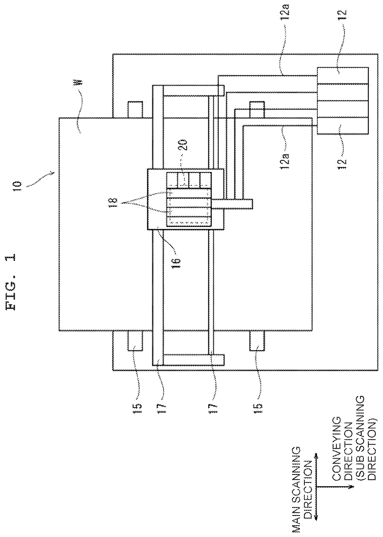
[0026]As depicted in FIG. 1, a liquid discharging head 20 of the present embodiment is provided on a liquid discharging apparatus 10. The liquid discharging apparatus 10 includes a storing tank 12, a carriage 16, a pair of conveying rollers 15, a pair of guide rails 17 and a sub tank 18, in addition to the liquid discharging head 20 configured to discharge liquid. Note that in the liquid discharging apparatus 10, a discharge medium W which is, for example, print paper (print paper sheet) is arranged ...


PUM


Abstract

A liquid discharging head includes: manifolds to which liquid is supplied; at least one nozzle row associated with each of the manifolds; and a communicating channel directly connecting two manifolds which are included in the manifolds and which are adjacent to each other. The at least one nozzle row includes nozzles configured to discharge the liquid, the nozzles communicating with one manifold with which the at least one nozzle row is associated. A first number is a number of the nozzle row associated with one of the two manifolds and a second number is a number of the nozzle row associated with the other of the two manifolds, and a cross-sectional area of the communicating channel is different between a case that a first number and a second number are same, and another case that the first number and the second number are different.

Description

CROSS REFERENCE TO RELATED APPLICATIONS[0001]The present application claims priority from Japanese Patent Application No. 2021-019166, filed on Feb. 9, 2021, the disclosure of which is incorporated herein by reference in its entirety,BACKGROUNDField of the Invention[0002]The present disclosure relates to a liquid discharging head discharging liquid such as ink, etc.BACKGROUNDDescription of the Related Art[0003]There is a conventionally known liquid discharging head having first to third supply manifolds which are arranged side by side in a main scanning direction. In this liquid discharging head, a plurality of nozzles are communicated with each of the first to third manifolds, and the plurality of nozzles form two nozzle rows. Each of the two nozzle rows extends along a longitudinal direction of one of the first to third supply manifolds. One ends in the longitudinal direction of the first to third supply manifolds are connected to a supply hole, and the other ends in the longitudi...

Claims


Application Information

Patent Timeline
IPC IPC(8): B41J2/14
CPCB41J2/14233B41J2002/14419B41J2002/14306
Inventor YAMAMOTO, JIROMORITA, YOSHITSUGUSEKIGUCHI, YASUHIRO
Owner BROTHER KOGYO KK
Learn More