
Exposure method for exposure device

An exposure method and technology of an exposure device, which are applied to exposure devices for photoengraving processes, microlithography exposure equipment, optics, etc., can solve the problems of time-consuming, difficult to apply, and time-consuming exposure.

Inactive Publication Date: 2006-11-08
ORC MFG
View PDF3 Cites 0 Cited by
  • Summary
  • Abstract
  • Description
  • Claims
  • Application Information

AI Technical Summary

Problems solved by technology

[0008] However, in the technique described in Patent Document 1, the alignment of the entire substrate is performed first, alignment is performed on any divided area in an appropriate order, and exposure is performed from the area where the alignment has been completed. Therefore, after dividing into four areas, In the case of , the calibration of the entire substrate requires five calibration steps, and even in the case of dividing into two areas, it is necessary to perform three calibration steps, which is time-consuming
[0009] Moreover, since the entire substrate is calibrated first by using the mask and the marks on the substrate, the error becomes larger after the calibration is performed on each area.
[0010] Since the technology described in Patent Document 2 is a method of measuring the center of gravity position of each pattern to be exposed and the center of gravity position of the whole, based on the measured data, correcting the reference position information of each of the plurality of regions, and based on the corrected data, , to expose each pattern, therefore, the exposure of each pattern takes time, and it is difficult to apply it to a device such as an exposure device for a printed circuit board that directly exposes the pattern of the mask by making the mask and the substrate close middle

Method used


Image

  • Exposure method for exposure device
  • Exposure method for exposure device
  • Exposure method for exposure device

Examples


Embodiment Construction

[0026] Hereinafter, embodiments of the exposure method of the exposure apparatus according to the present invention will be described with reference to the drawings.

[0027] The present invention is an exposure method of an exposure apparatus, which aligns a substrate having a plurality of calibration marks for positioning, and a mask having mask marks for aligning positions with the calibration marks and a mask provided with a predetermined pattern. Exposure is performed with the mask in close contact with the substrate.

[0028] First, the exposure apparatus which is the premise of an exposure method is demonstrated.

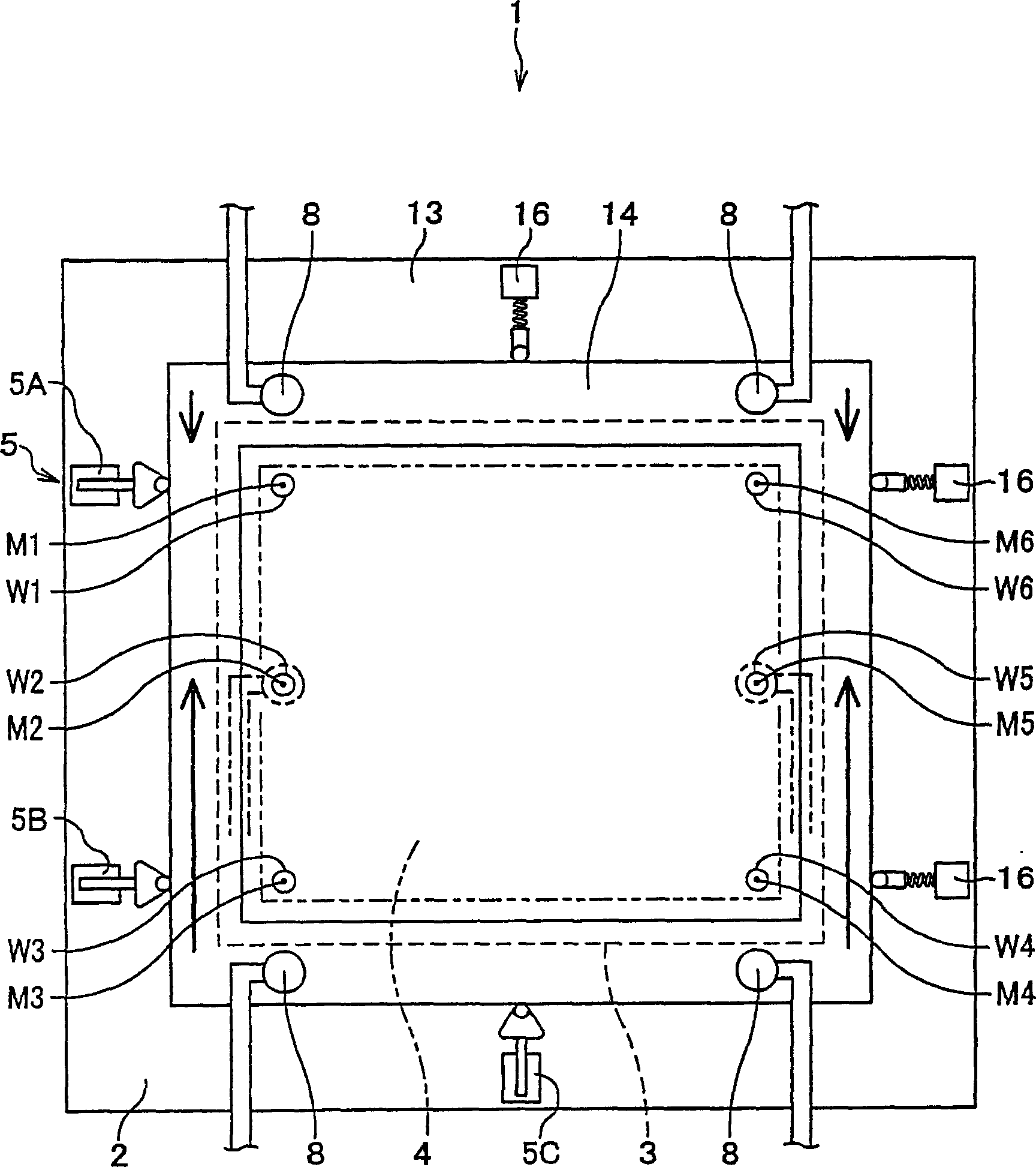
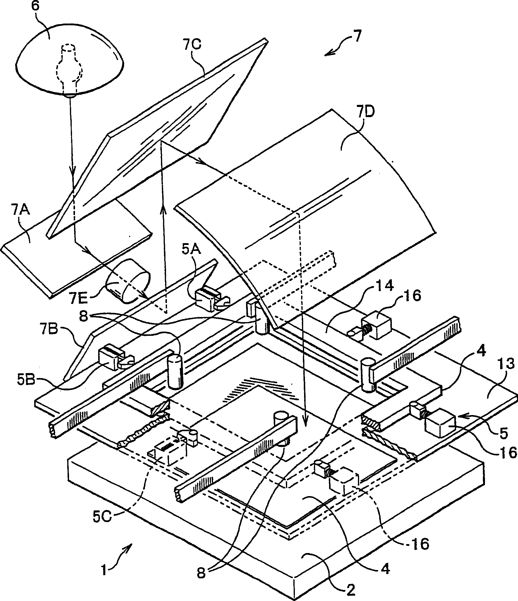
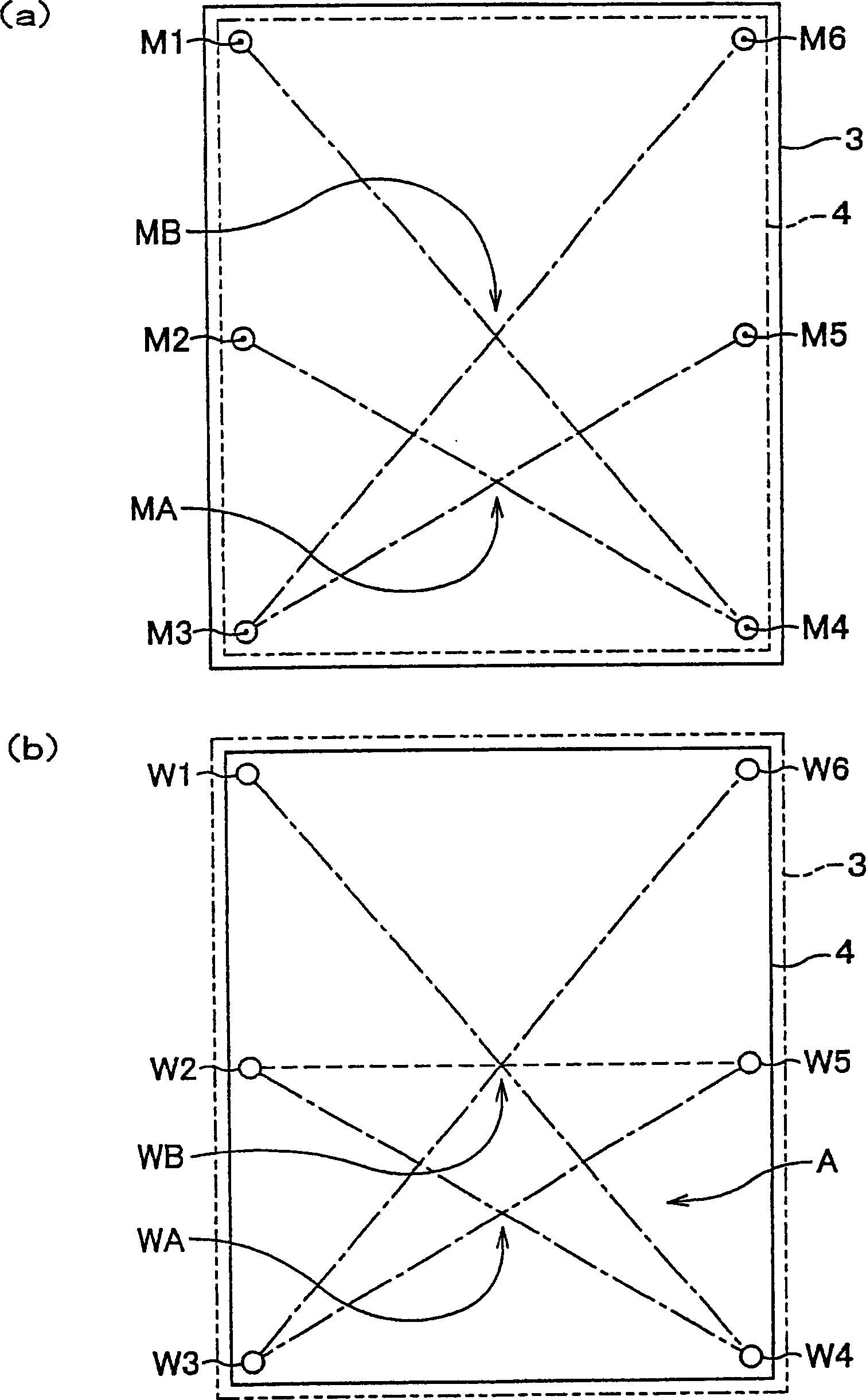
[0029] In the attached drawings, figure 1 It is a plan view showing main parts of the exposure apparatus. FIG. 2 is a schematic perspective view of the entire exposure device. image 3 (a) is a schematic diagram showing the arrangement of mask marks on the mask. image 3 (b) is a schematic diagram showing the arrangement of alignment marks on the substrate...


PUM


Abstract

The present invention provides an exposure method of an exposure device capable of accurately aligning a substrate and a mask in a short process and rapidly exposing the entire substrate. It calibrates a substrate with calibration marks and a mask with mask marks and a predetermined pattern, and performs exposure in a state where the mask is closely attached to the substrate. The step of assigning points MA and MB obtained by intersecting diagonal lines of half area and the whole; based on the calibration mark, calculating the distribution points WA and WB obtained by intersecting diagonal lines of half area of ​​the substrate and the whole step; a comparison step of comparing the distribution point MB with the distribution point WB; through the comparison step, a judgment step of judging whether the distribution point WB is within the allowable range relative to the distribution point MB; and when the judgment step judges that it is within the allowable range, the A step of irradiating the entire substrate with exposure light.

Description

technical field [0001] The invention relates to an exposure method of substrates such as printed circuit boards and liquid crystal substrates and masks, in particular to an exposure method of an exposure device that performs exposure operations according to distribution points (points) between masks and substrates. Background technique [0002] Patent Document 1: Japanese Unexamined Patent Publication No. 11-194507 (paragraphs 0011-0014, image 3 ) [0003] Patent Document 2: Japanese Unexamined Patent Publication No. 2000-122303 (full text) [0004] Conventionally, when producing a printed circuit board, an exposure device is used which aligns a mask provided with a circuit pattern with a substrate, and then irradiates exposure light in a state in which the two are in close contact, so that the pattern of the circuit is aligned. copied to the substrate. [0005] Such an exposure apparatus has: a base on which a substrate is placed; a mask having a predetermined pattern an...

Claims


Application Information

Patent Timeline
Patent Type & Authority Patents(China)
IPC IPC(8): G03F7/20G03F9/00H01L21/027
Inventor 屋木康彦薮慎太郎氏益稔
Owner ORC MFG
Learn More