
Exposal system and control method thereof

A technology of exposure system and control method, which is applied in microlithography exposure equipment, photolithography exposure device, optics, etc., and can solve the problems of increased moving distance, long time, increased production cost, etc.

Active Publication Date: 2009-04-29
SAMSUNG ELECTRONICS CO LTD
View PDF0 Cites 0 Cited by
  • Summary
  • Abstract
  • Description
  • Claims
  • Application Information

AI Technical Summary

Problems solved by technology

[0008] However, in the case of the above-mentioned conventional exposure system disclosed in Korean Patent Publication No. 2005-0012163, since the system includes a single optical module assembly and thus has only one overlay measuring instrument, the scan time required to measure the substrate overlay very long
In addition, the moving distance of the substrate for the scanning operation increases, so a large-sized expansive mounting table is required and results in an increase in the overall production cost
[0009] Moreover, since the longer the scan time, the more error parameters, the exposure system inevitably has degraded exposure accuracy
[0010] However, another problem of the above-mentioned conventional exposure system is that when the substrates have exposure regions of different sizes (hereinafter, the exposure regions refer to regions on the substrate where the exposure operation should be performed), it takes an extremely long time to perform the exposure operation on the substrate.

Method used


Image

  • Exposal system and control method thereof
  • Exposal system and control method thereof
  • Exposal system and control method thereof

Examples


Embodiment Construction

[0030] Now, exemplary embodiments of the present invention will be described in detail, examples of which are illustrated in the accompanying drawings, wherein like reference numerals refer to like elements throughout. The embodiments are described below in order to explain the present invention by referring to the figures.

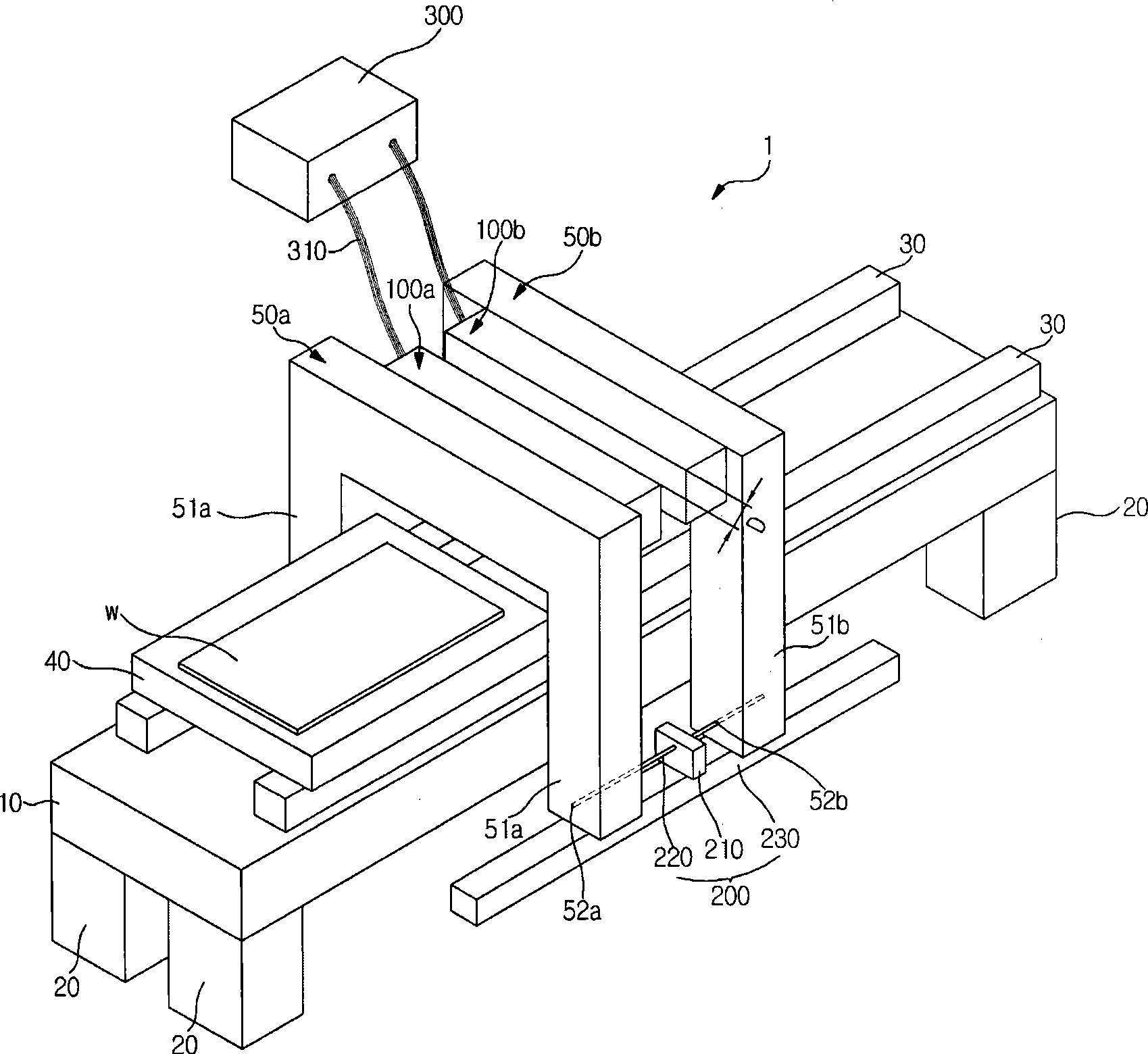
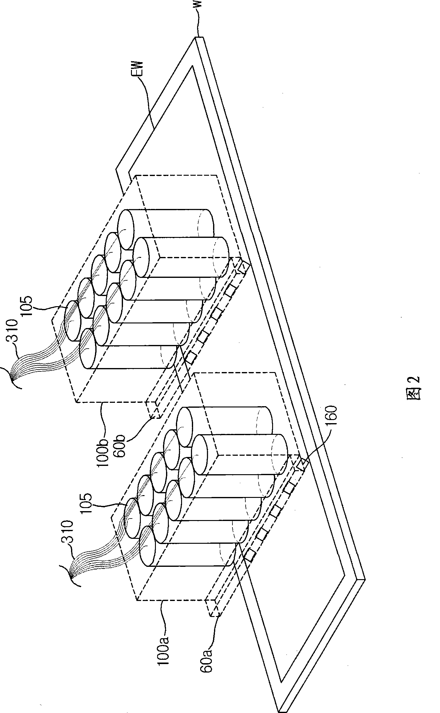
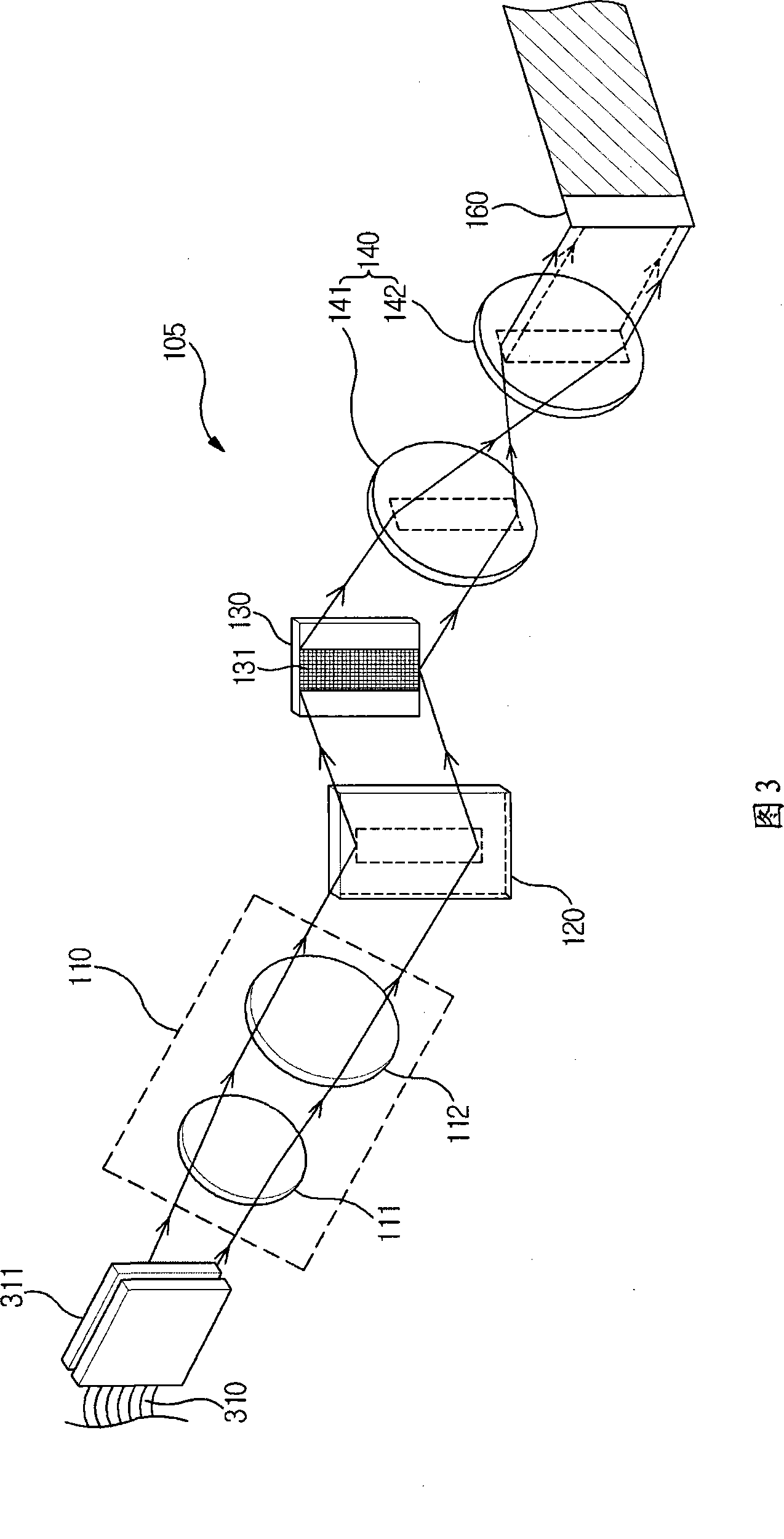
[0031] refer to figure 1 4, the exposure system 1 according to the present invention to be installed in a vacuum chamber includes: a mounting table 10 supported by pillars 20 extending downward from four corners of the mounting table 10; a stand 40 along the mounting table The direction of the longer side of 10 is movably arranged on the mounting table 10, and has a top surface on which the substrate W will be placed; a stage drive unit 70 is installed on the top surface of the mounting table 10 to move the stage 40; A stand guide 30 is installed on the top surface of the mounting stand 10 to guide the direction of movement of the stand 40; a plurality o...


PUM


Abstract

The invention claims an exposure system capable of reducing scan time and scan distance and a control method thereof. Low cost of production may be implemented and exposure accuracy may be improved by using the exposure system and control method thereof. Moreover, rapid exposure of a substrate of exposure regions with different sizes may be implemented. The exposure system has several optic module components used for radiating lights with patterns onto exposure regions that differ from each other. The optic module components are arranged to permit adjustment of space distance there-between. Control method of the exposure system comprises the following steps: determining whether the exposure mode is changed; and adjusting space distance between several optic module components according to the changed exposure mode if it is.

Description

[0001] This application claims the benefit of Korean Patent Application No. 2007-0105929 filed with the Korean Intellectual Property Office on October 22, 2007, the disclosure of which is incorporated herein by reference. technical field [0002] The present invention relates to an exposure system and a control method thereof, and more particularly, to an exposure system and a control method thereof capable of reducing scanning time and scanning distance, thereby achieving low production cost and improved exposure accuracy , and perform fast exposures of substrates with exposure areas of various sizes. Background technique [0003] In general, there are various well-known methods to achieve pattern drawing by irradiating light to a semiconductor substrate or a glass substrate (hereinafter, referred to as "substrate") formed on, for example, a liquid crystal display or a plasma display. Photosensitive materials come up to realize. Examples of conventional methods of transfer...

Claims


Application Information

Patent Timeline
IPC IPC(8): G03F7/20
CPCG03F7/70791G03F7/70275G03F7/70258
Inventor 金乙泰李成进朴相玄裴祥佑
Owner SAMSUNG ELECTRONICS CO LTD
Learn More