Electric valve controller

A valve controller, electric valve technology, applied in valve details, valve devices, engine components, etc., can solve the problems of mechanical contact failure, valve and its equipment damage, etc., to avoid the effect of valve stem top bending and damage

Inactive Publication Date: 2006-12-20
孟锋
View PDF0 Cites 0 Cited by
  • Summary
  • Abstract
  • Description
  • Claims
  • Application Information

AI Technical Summary

Problems solved by technology

The mechanical contact of the limiter is easy to cause failure, and if the torque exceeds the limit, it will cause damage to the valve and its equipment

Method used


Image

  • Electric valve controller
  • Electric valve controller
  • Electric valve controller

Examples


Embodiment Construction

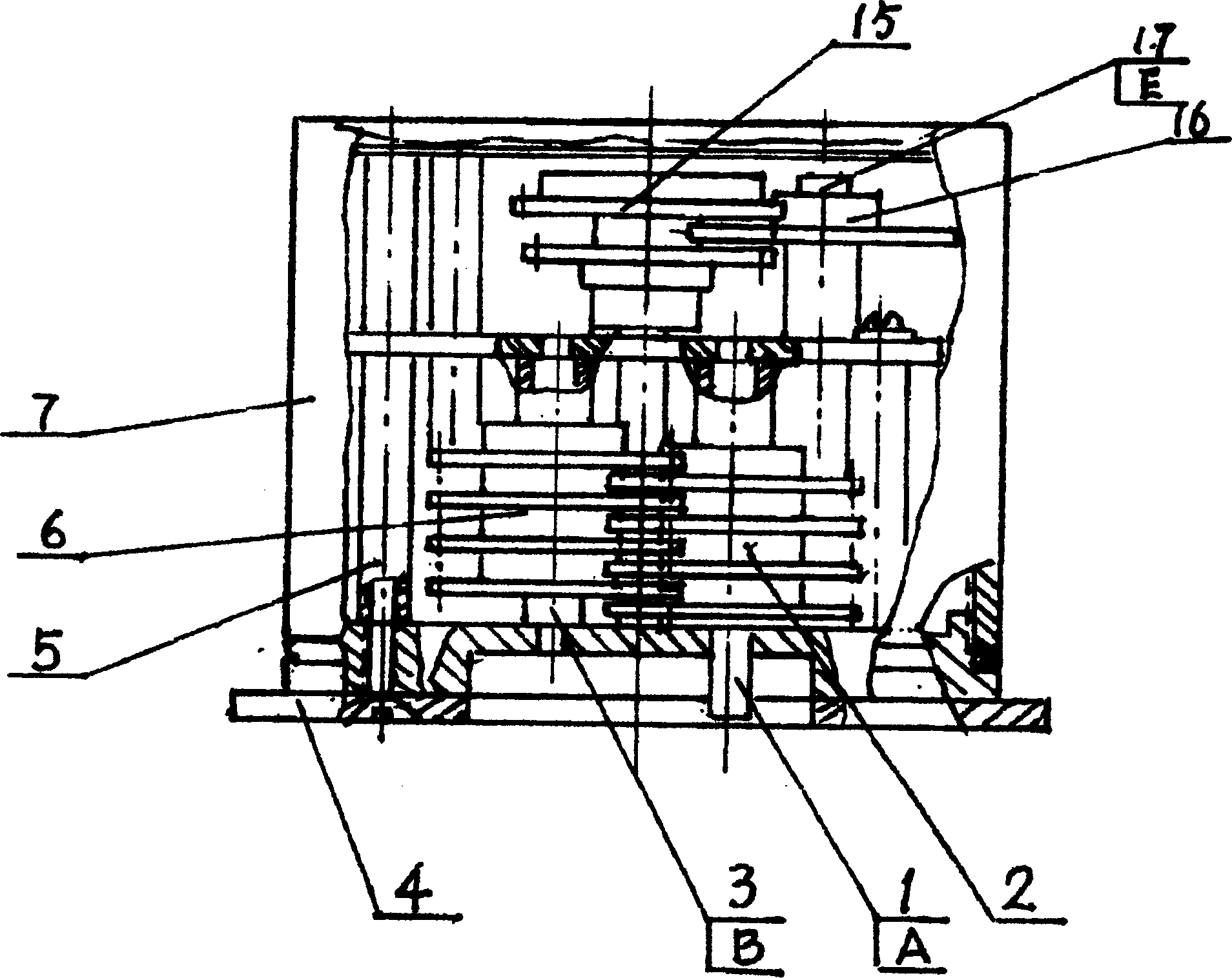
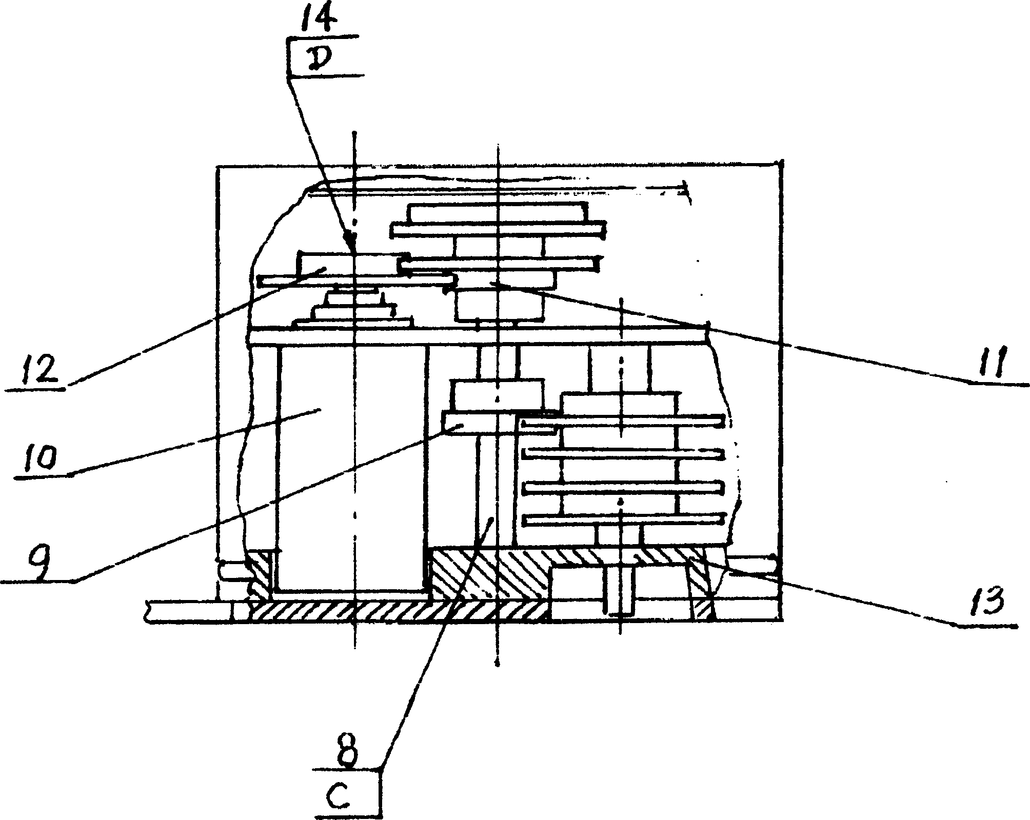
[0013] Electric valve controllers, including valve position transmitters and valve controllers. The valve position transmitter includes a housing 7, a bottom plate 4, a bearing frame 13, a bracket 5, a transmission shaft, a stroke gear set 2, a stroke gear set 6, an intermediate gear 9, a position transmission gear 11 and a potentiometer 10. Stroke gear set 2 is mounted on A-axis 1, stroke gear set 6 is mounted on B-axis 3, stroke gear set 2 and stroke gear set 6 mesh with each other, intermediate gear is mounted on C-axis 8, position transmission gear 11 is mounted on C-axis On the upper end of the shaft 8, the position transmission driven gear 12 is installed on the D shaft 14, and the intermediate gear 9 is selectively meshed with one of the stroke gear set 2 and the stroke gear set 6 according to the digital ratio, and the position transmission gear 11 mounted on the C axis 8 and The position transmission driven gear 12 mounted on the D shaft 14 is engaged, and the potenti...


PUM


Abstract

The electric valve controller includes valve position transducer and valve controller. The valve position transducer has stroke gear set meshed with the middle gear and input shaft or shaft A connected to the main valve lead screw, and transmits via the gear set, the position driving gear on shaft C and position driven gear on shaft D. The potentiometer connected onto the shaft A sends out the valve position signal and has its lead out lines connected to the electric valve controller for opening and closing. The present invention has the advantages of automatic digital display of valve opening and closing state and thus accurate control and less damage.

Description

(1) Technical field [0001] The invention relates to a controller for opening and closing an electric valve, in particular to an electric valve controller using digital display and digital control. (2) Background technology [0002] Electric valves are mainly used in power generation, steel, petroleum, chemical, tap water and other industries. Existing electric valves mainly use limiters to cut off the control circuit of the running motor to achieve the purpose of opening and closing. This control method can only control the full opening and full closing of the valve, and its operation process is like a blind man feeling the elephant. He does not know the position of the valve, and the purpose of arbitrary control cannot be achieved. The mechanical contact of the limiter is easy to cause failure, and if the torque exceeds the limit, it will cause damage to the valve and its equipment. (3) Contents of the invention [0003] The technical problem to be solved by the present...

Claims


Application Information

Patent Timeline
Patent Type & Authority Patents(China)
IPC IPC(8): F16K31/04F16K31/53F16K37/00
Inventor 白洪发孟华孟锋
Owner 孟锋
Why Eureka
Try Eureka