Lens assembly
A lens assembly, lens technology, applied in the direction of lenses, optical components, instruments, etc., can solve the problem that the clamping device is not practical enough
- Summary
- Abstract
- Description
- Claims
- Application Information
AI Technical Summary
Problems solved by technology
Method used
Image
Examples
Embodiment 1
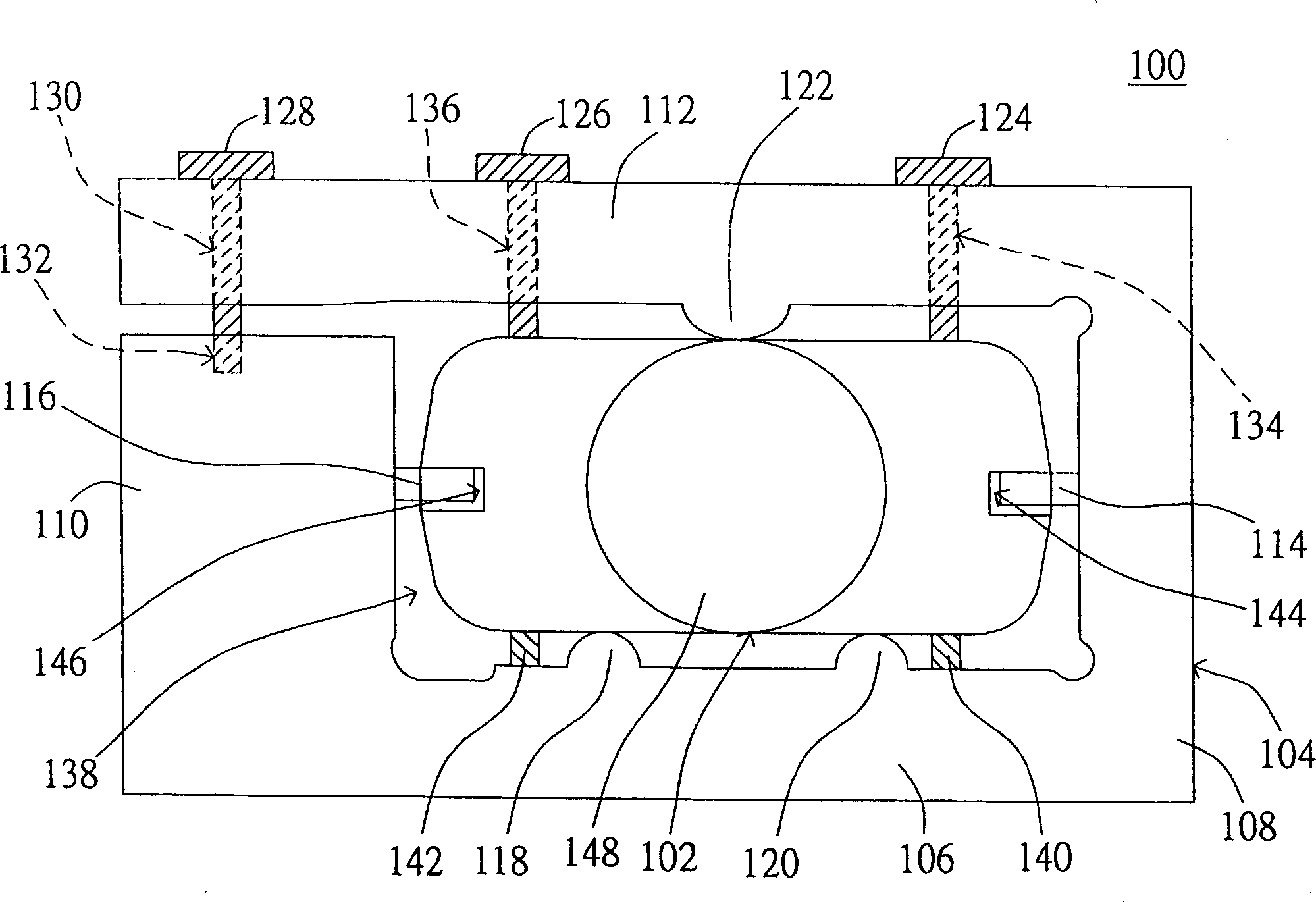
[0018] Please refer to figure 1 , which is a side view of the lens assembly 100 according to Embodiment 1 of the present invention. exist figure 1 Among them, the lens assembly 100 includes a lens 102 and a clamping device 104. The clamping device 104 is configured in an optical machine for clamping the lens 102 in the optical machine so that the lens 102 can accurately feed light and focus imaging.
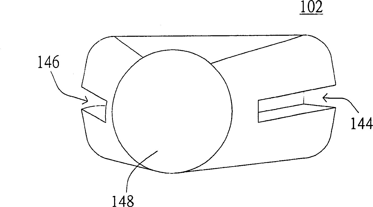
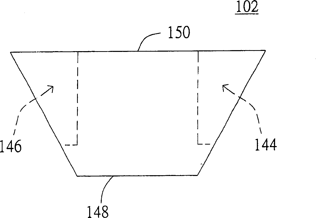
[0019] Both sides of the lens 102 have a first chute 144 and a second chute 146, and the lens 102 has a light feed-in end 148, such as Figure 2A and Figure 2B shown. in, Figure 2A It is shown that the lens 102 is a triangular pyramid structure. certainly, Figure 2B The lens 102 also has an image feed-out end 150 opposite to the light feed-in end 148 . Please refer to figure 1 The lower side of the lens 102 has a first elastic element 140 and a second elastic element 142 for providing elastic force between the lens 102 and the clamping device 104 to achieve shockproof ...
Embodiment 2
[0029] Please refer to image 3 , which is a side view of the lens assembly 300 according to Embodiment 2 of the present invention. exist image 3 Among them, the lens assembly 300 includes a lens 302 and a clamping device 304. The clamping device 304 is configured in an optical machine for clamping the lens 302 in the optical machine so that the lens 302 can accurately feed light and focus imaging.
[0030] Both sides of the lens 302 have a first extension 314 and a second extension 316, and the lens 302 has a light feeding end 348, such as Figure 4A and Figure 4B shown. in, Figure 4A It is shown that the lens 302 is a triangular cone-shaped structure. certainly, Figure 4B The lens 302 also has an image feed-out end 350 opposite to the light feed-in end 348 . Please refer to image 3 The lower side of the lens 302 has a first elastic element 340 and a second elastic element 342 for providing elastic force between the lens 302 and the clamping device 304 to achieve...
PUM
 Abstract
Description
Claims
Application Information
 - R&D
- Intellectual Property
- Life Sciences
- Materials
- Tech Scout
- Unparalleled Data Quality
- Higher Quality Content
- 60% Fewer Hallucinations
Browse by: Latest US Patents, China's latest patents, Technical Efficacy Thesaurus, Application Domain, Technology Topic, Popular Technical Reports.
© 2025 PatSnap. All rights reserved.Legal|Privacy policy|Modern Slavery Act Transparency Statement|Sitemap|About US| Contact US: help@patsnap.com


