
Placode processor and liquid feeder

A technology for a substrate processing device and a liquid feeding device, which is applied in door/window protection devices, devices for coating liquid on surfaces, and liquid variable volume machines, etc. Problems such as particle mixing, etc., to achieve the effect of easy cleaning and other maintenance, easy drainage, and reduced attractiveness

Active Publication Date: 2007-01-17
DAINIPPON SCREEN MTG CO LTD
View PDF6 Cites 1 Cited by
  • Summary
  • Abstract
  • Description
  • Claims
  • Application Information

AI Technical Summary

Problems solved by technology

There is a question of when the pump needs to be maintained
[0013] In addition, since the driving mechanism (motor 131, screw 132, and nut member 133) that moves the piston 112 has low machining accuracy and control accuracy, the feeding accuracy of the nut member 133 (piston 112) is low. question
[0014] Furthermore, due to the driving of the piston valve 110, the sealing member 113 is worn by friction with the cylinder body 111, and there is a problem that the resulting particles are mixed in the treatment liquid or the sealing member 113 must be replaced periodically.

Method used

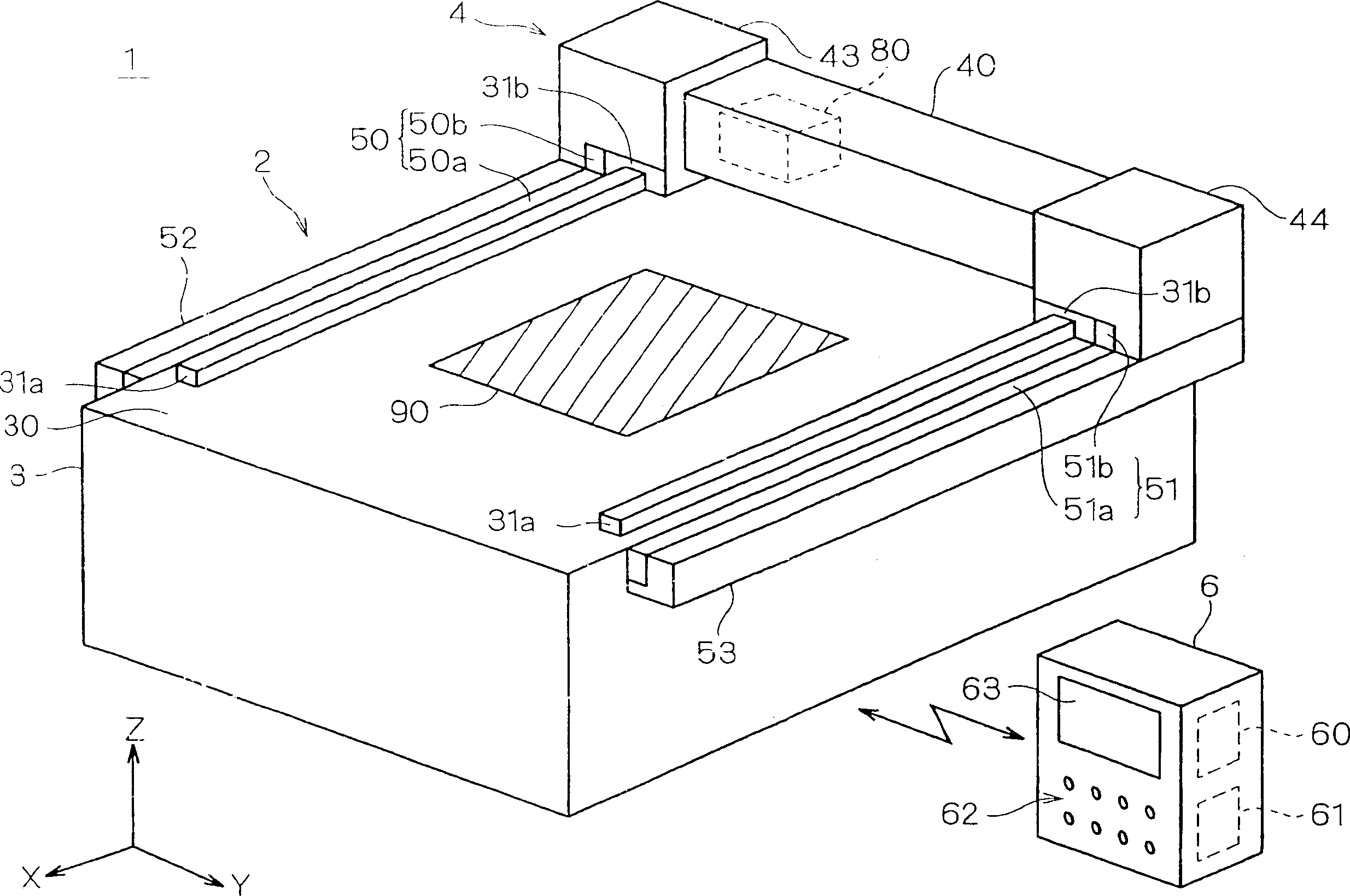
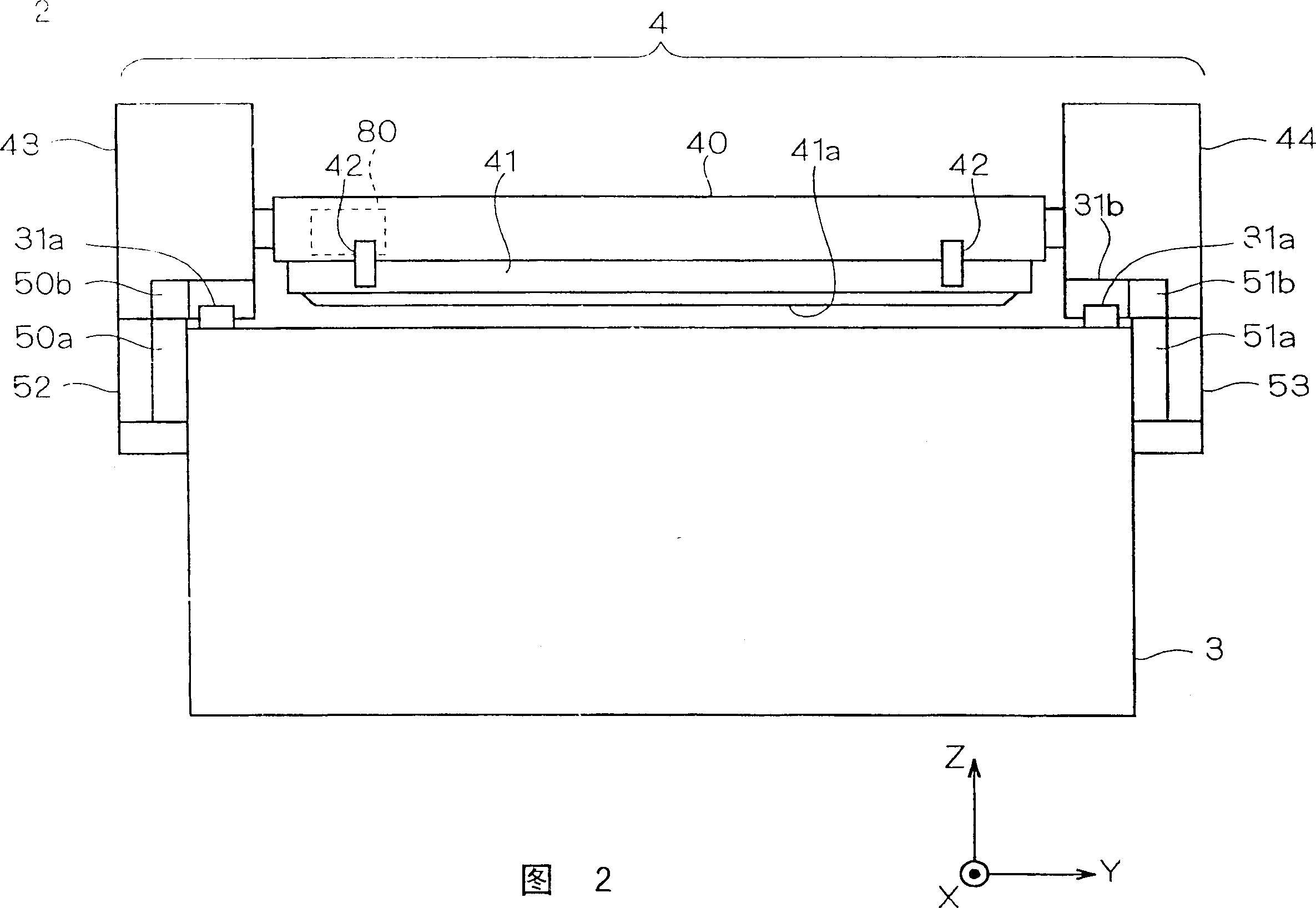
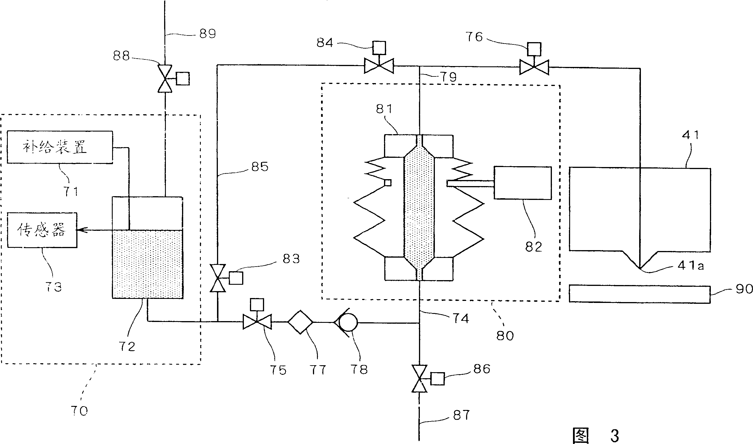

Image

  • Placode processor and liquid feeder
  • Placode processor and liquid feeder
  • Placode processor and liquid feeder

Examples


no. 2 Embodiment approach

[0179] In the substrate processing apparatus 1 according to the first embodiment, the resist liquid is sent to the slit nozzle 41 by one resist liquid pump 81 . Here, when the volume of the substrate 90 to be processed is large and it is necessary to increase the discharge amount per one pass of the coating process, conventionally, the resist solution pump 81 has been replaced with a large pump with a large discharge amount. . However, it is difficult to manufacture such a large pump with high precision, and as a result, there is a problem that the coating accuracy is lowered. In the present invention, like the substrate processing apparatus 1 shown in the first embodiment, the pump for feeding the resist liquid is not limited to one, but may be plural.

[0180] Figure 6 It is a diagram showing the connection relationship between the liquid feeding mechanism 80 a and the slit nozzle 51 of the substrate processing apparatus 1 according to the second embodiment configured bas...

no. 3 Embodiment approach

[0206] The substrate processing apparatus 1 of the second embodiment has two drive mechanisms 82a, 82b for driving the two protection pumps 81a, 81b, and the respective drive mechanisms 82a, 82b independently drive the respective resist liquid pumps 81a, 81b. Therefore, the control system 6 controls the drive units 82a and 82b in synchronization so that the discharge flow rates of the resist liquid pump 81a and the resist liquid pump 81b are equal. However, the method of synchronously driving the two resist liquid pumps 81a and 81b is not limited to the case of being controlled by the control system 6, and may be performed mechanically, for example.

[0207] Figure 8 It is a schematic diagram of the connection relationship between the liquid feeding mechanism 80b and the slit nozzle 41 of the substrate processing apparatus 1 according to the third embodiment configured based on this principle. In addition, in the substrate processing apparatus 1 of this embodiment, the struc...


PUM


Abstract

Provided are an apparatus for transferring the resist solution, which do not generate particles and transfer the resist solution with high precision. A resist pump and a driving equipment are installed to a transferring equipment which transfers a resist solution to a slit nozzle. A first bellows having a smaller diameter, a second bellows having a larger diameter, a coupling member for the first and second bellows and a tube as a flow passage of the resist solution are installed to the resist pump. By allowing the moving member to be moved downward by the driving equipment, the inner volume of the tube is decreased, thereby the resist solution at the inner tube being transferred to the slit nozzle. By allowing the coupling member to be moved downward by the driving equipment, the inner volume of the tube is increased, thereby the resist solution is absorbed in the resist pump.

Description

technical field [0001] The present invention relates to a technique for feeding a treatment liquid coated on a substrate. Background technique [0002] When coating a processing liquid such as a resist liquid on a substrate, it is known to use various pumps such as a syringe pump (piston pump), a bellows pump (bellows pump), a gear pump, or a diaphragm pump to spray the resist liquid The feeding device and the pressure-feeding device that feeds the resist solution with a certain pressure, etc. [0003] In particular, in a slit coater that applies a resist solution through a slit nozzle, the film of the resist solution coated on the substrate is determined by the moving speed of the slit nozzle and the amount of resist solution supplied. thick. Therefore, in order to control the film thickness of the resist liquid with high precision, bellows pumps or piston pumps have been used conventionally. [0004] However, since the structure of the bellows pump unavoidably tends to ...

Claims


Application Information

Patent Timeline
Patent Type & Authority Patents(China)
IPC IPC(8): B05C5/02B05C11/10F04B7/00B05C5/00
CPCA61L2202/25D02G3/449E06B9/52E06B2009/524E06B2009/527
Inventor 高木善则福地毅北泽裕之安藤美奈子
Owner DAINIPPON SCREEN MTG CO LTD
Learn More