Supercharge Your Innovation With Domain-Expert AI Agents!

Surface matrix type pit machining method and apparatus

A processing device and matrix technology, applied in metal processing equipment, milling devices that can be installed on machine tools, manufacturing tools, etc., can solve problems such as difficult processing, low efficiency, and long processing time of parts, and achieve uniform distribution and regular arrangement good performance and improve the overall efficiency

Inactive Publication Date: 2007-02-07
王爱玲
View PDF5 Cites 0 Cited by
  • Summary
  • Abstract
  • Description
  • Claims
  • Application Information

AI Technical Summary

Problems solved by technology

However, because it adopts a hammering method, it is a micro-pit formed after metal deformation, and the edge of the micro-pit will be raised, so it needs honing and other processes for reprocessing
Therefore, the processing time of parts is longer and the efficiency is lower
For parts with high surface hardness, it is also difficult to process with this method.

Method used


Image

  • Surface matrix type pit machining method and apparatus
  • Surface matrix type pit machining method and apparatus
  • Surface matrix type pit machining method and apparatus

Examples


Embodiment Construction

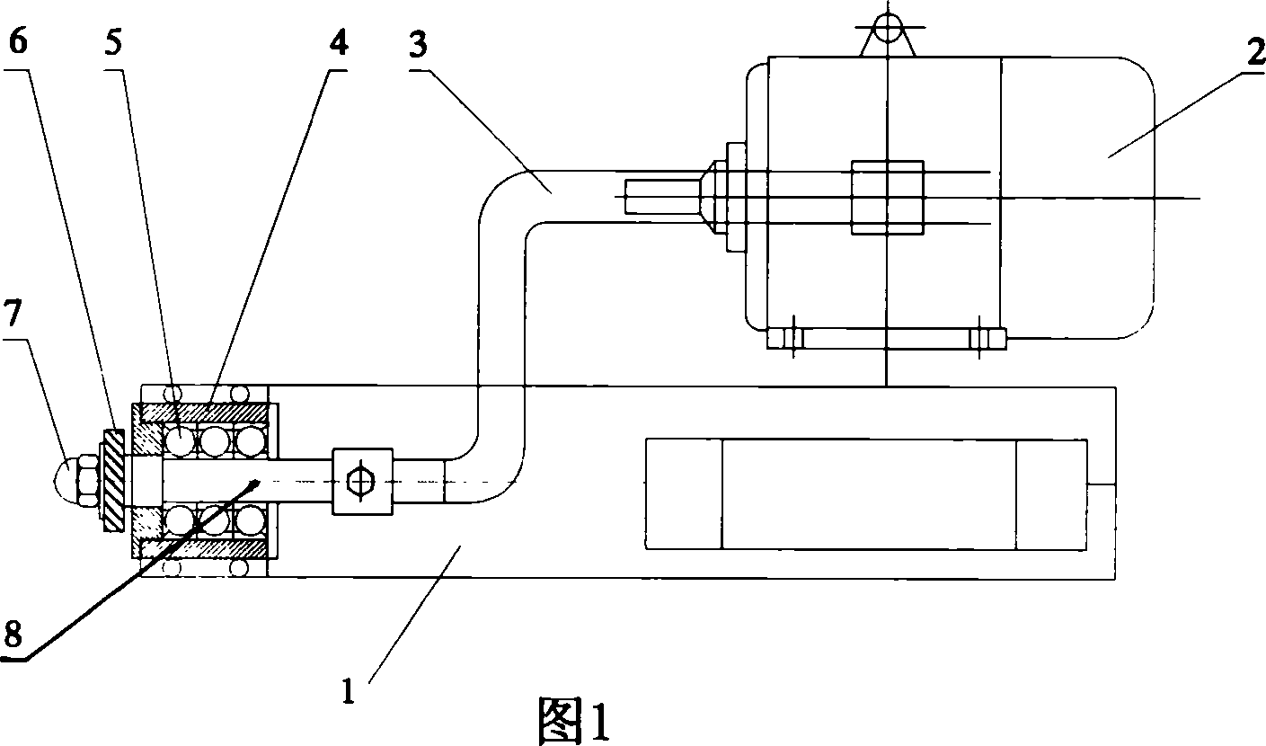
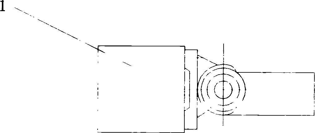
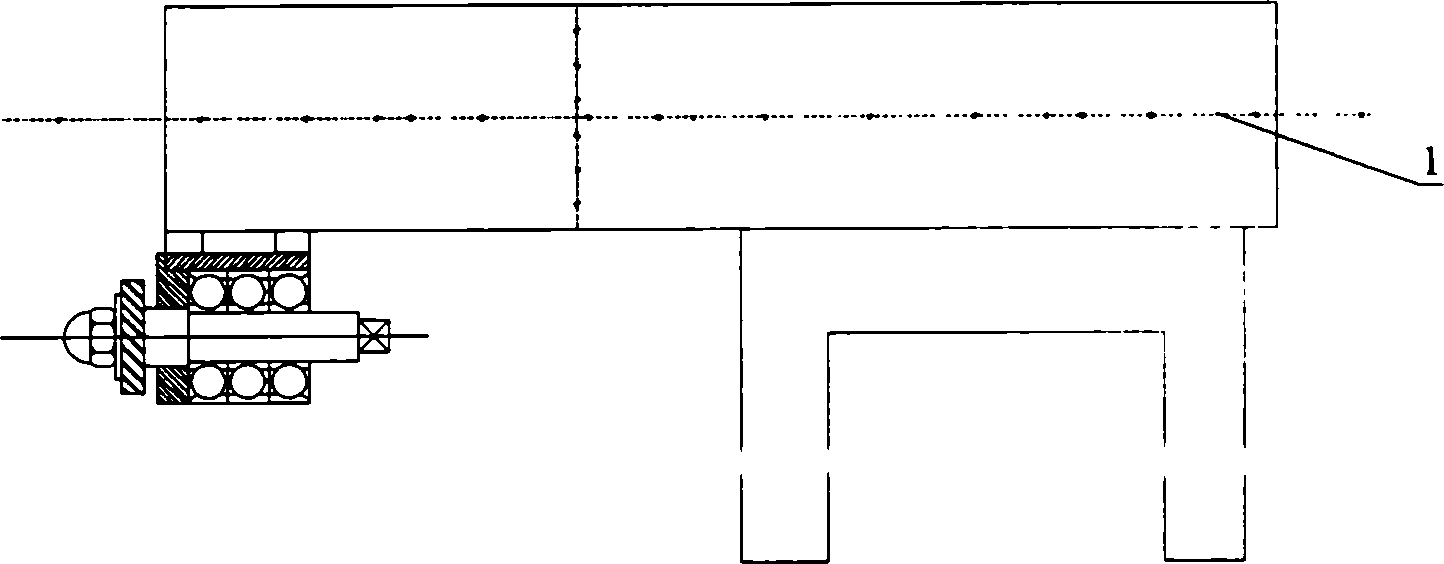
[0012] figure 1, figure 2 and image 3 As shown, the surface matrix micropit processing device of the present invention includes: a tool holder 1 , a motor 2 , and a transmission shaft 3 . There is a rotary shaft 8 on the cutter bar, and the rotary shaft belt bearing 5 is installed in the bearing seat 4, and the bearing seat is fixed on the cutter bar by bolts; Milling cutter 6 is installed before the rotating shaft, and is fastened by cap nut 7.

[0013] Figure 4 As shown, the milling cutter of the surface matrix micropit processing device has a diameter of 16 to 40 mm, and the number of teeth: 4, 6, 8, 12, 16, etc.

[0014] The following is the process of processing the cylinder liner using the surface matrix micro-pit processing device:

[0015] The cylinder liner is installed on the main shaft of the lathe, the tool bar 1 is installed on the small tool holder of the lathe slide box, the motor 2 is installed at the tailstock of the lathe, and the motion is transmitted ...


PUM


Abstract

The invention is a surface matrix micro pit processing method and device. It includes: arbor, motor, gearing axis. The arbor has a rotation axis, the rotation bearing is assembled in the bearing base, the bearing base is fixed on the arbor with screw; the motor is connected to the rotation axis with soft axis, there has a milling cutter at the front part of the arbor, and it is fixed by cover screw. The milling cutter processes the surface of the piece, the milling cutter rotates, and moves relatively to the piece, and carries on movement vertical to the piece, thus the micro pit can be processed under effect of the three kinds of movements. The invention upgrades the process efficiency of the part.

Description

technical field [0001] The invention belongs to the field of mechanical processing, and relates to a device for processing matrix-type micro-pits on the surface of friction pair parts by using a cutter. Background technique [0002] In mechanical equipment, there are various friction pairs to achieve different motions and functions. In order to reduce the friction force and wear of the friction pair and improve the service life of the friction pair parts, people have adopted various lubricating oils and methods and structures for preserving the lubricating oil in the friction pair. Such as improving the surface hardness, precision and roughness of friction pair parts, opening oil grooves, grooves or immersing in oil pools, etc. In recent years, for the theory of tribology, a relatively new microelastic tribology theory has been proposed. There are regularly arranged micropits on the surface of the friction pair parts to increase the oil storage of the friction pair to ensur...

Claims


Application Information

Patent Timeline
Patent Type & Authority Patents(China)
IPC IPC(8): B23C7/02B23C7/00
Inventor 祝锡晶谢解春王爱玲孙旭东翟宁
Owner 王爱玲
Features
  • R&D
  • Intellectual Property
  • Life Sciences
  • Materials
  • Tech Scout
  • Unparalleled Data Quality
  • Higher Quality Content
  • 60% Fewer Hallucinations
Learn More