Visual data integration system and method

A technology of information systems and components, applied in the field of information systems, can solve problems such as not being suitable for reliable and efficient transmission of massive data, complex work, and limitations

Inactive Publication Date: 2001-07-04
ADC TELECOMMUNICATIONS
View PDF0 Cites 10 Cited by
  • Summary
  • Abstract
  • Description
  • Claims
  • Application Information

AI Technical Summary

Problems solved by technology

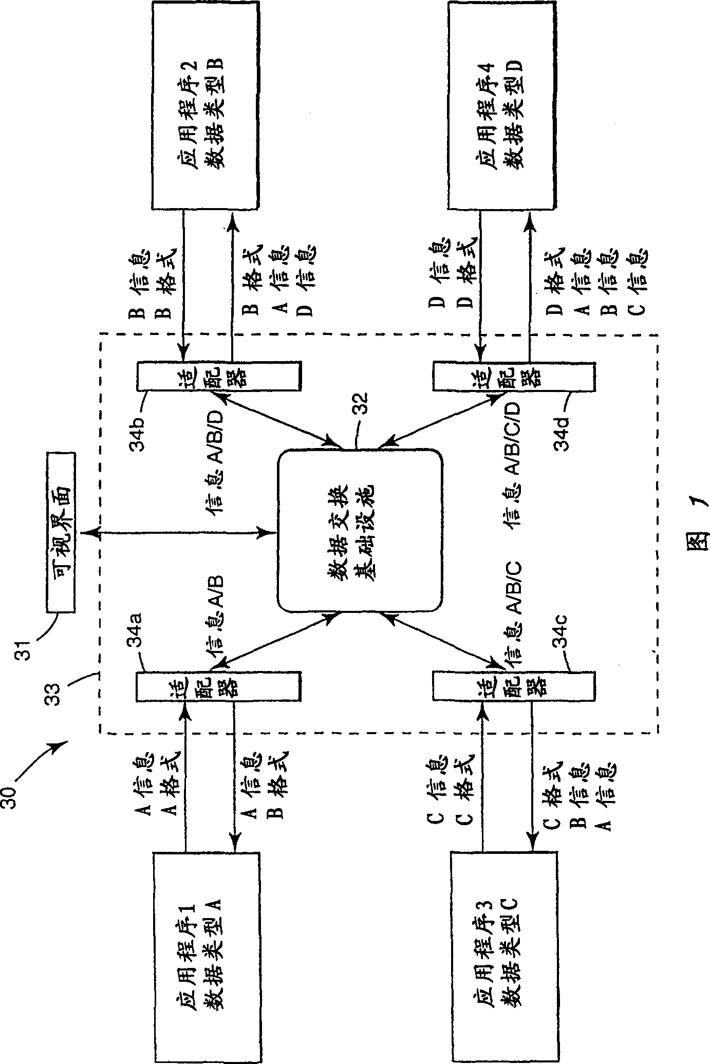
4th and 5th generation languages ​​are not well suited for reliable and efficient transfer of large amounts of data from one application to another or multiple applications
during the design and configuration phases, such incompatibility issues typically limit the ability of users to effectively inter-operate with traditionally implemented integrated information systems and significantly overwhelm the effort to extract useful system and mission integration / management information from said systems complication

Method used


Image

  • Visual data integration system and method
  • Visual data integration system and method
  • Visual data integration system and method

Examples


example 1

[0150] public class DX_Graph extends Thread{--> public DX_Graph(char *Qname,int viewld){ this.viewld = viewld; this.Qname=Qname;} public void run(){ switch(viewld){ case SystemManagementView: DrawSystemManagementViewWindow(); Case Business Management View: DrawBusinessManagementView(); Default; } } public void DrawSystemManagementViewWindow(){ Construct the eonfiguration form Construct the tabbed pane with tabs: (create a tabbed pane with the following tabs) "Incoming","Incoming Rate","Outgoing","Out Rate", "Backlog", the default subsection is "Incoming". The sub panes are: (the sub-panes are) DrawEnqGraph(Qname,displayPeriod) DrawDeQGraph(Qname,displayPeriod) DrawBacklog(Qname,displayPeriod) ………} public void DrawBusinessManagementViewWindow(){ Construct the configuration form Construct ...

example 2

[0185] GetEmployeeId(input object) EmployeeName|DX_STRING|MANDATORY|256| RequestOperation (optional modifiable internal SQL operation provided by the adapter developer) GetEmployeeId="When EmployeeName= Select from Employees" GetEmployeeIdResponse(output object) EmployeeId|DX_INTEGER|MANDATORY|0-9999999|

[0186] As previously mentioned, and as Figure 18 As shown, when using the visual interface 501 to configure a data integration project, the user generally selects at least two adapters, and then connects them with a straight line representing a queue. When the straight line connects the two adapters, the user interface 501 performs a meta-model query for each adapter and then compares them. If the models do not match, the color of the connection line or other visual feature is changed to warn the user that the two models cannot be "plug and play" without some degree of specialized mapping.

[0187] When the user wishes to perform mapping, the vis...

example 3

[0194] Project File.sxp

[0195] [project configuration (project configuration)]

[0196] %Storage type, File storage or other database storage is acceptable

[0197] % Note: copy to .cfg when setting

[0198] Storage Type=[FILE]|[ORACLE]

[0199] % The name of the error queue used for this project

[0200] % Note: copy to .cfg when setting

[0201] Error Queue=

[0202] % For each component, there is a group starting with "[instance name (instance name)]"

[0203] % Instances defined in this project

[0204] [instance name (instance name)]

[0205] % The name of the component to display in the "system window" of the UI

[0206] System Name=

[0207] % The name of the component to display in the "system window" of the UI

[0208] Business Name=

[0209] % The x coordinate where the icon is located (increasing from left to right)

[0210] X-Coordinate=

[0211] % The Y coordinate where the icon is located (increasing from top to bottom)

...


PUM


Abstract

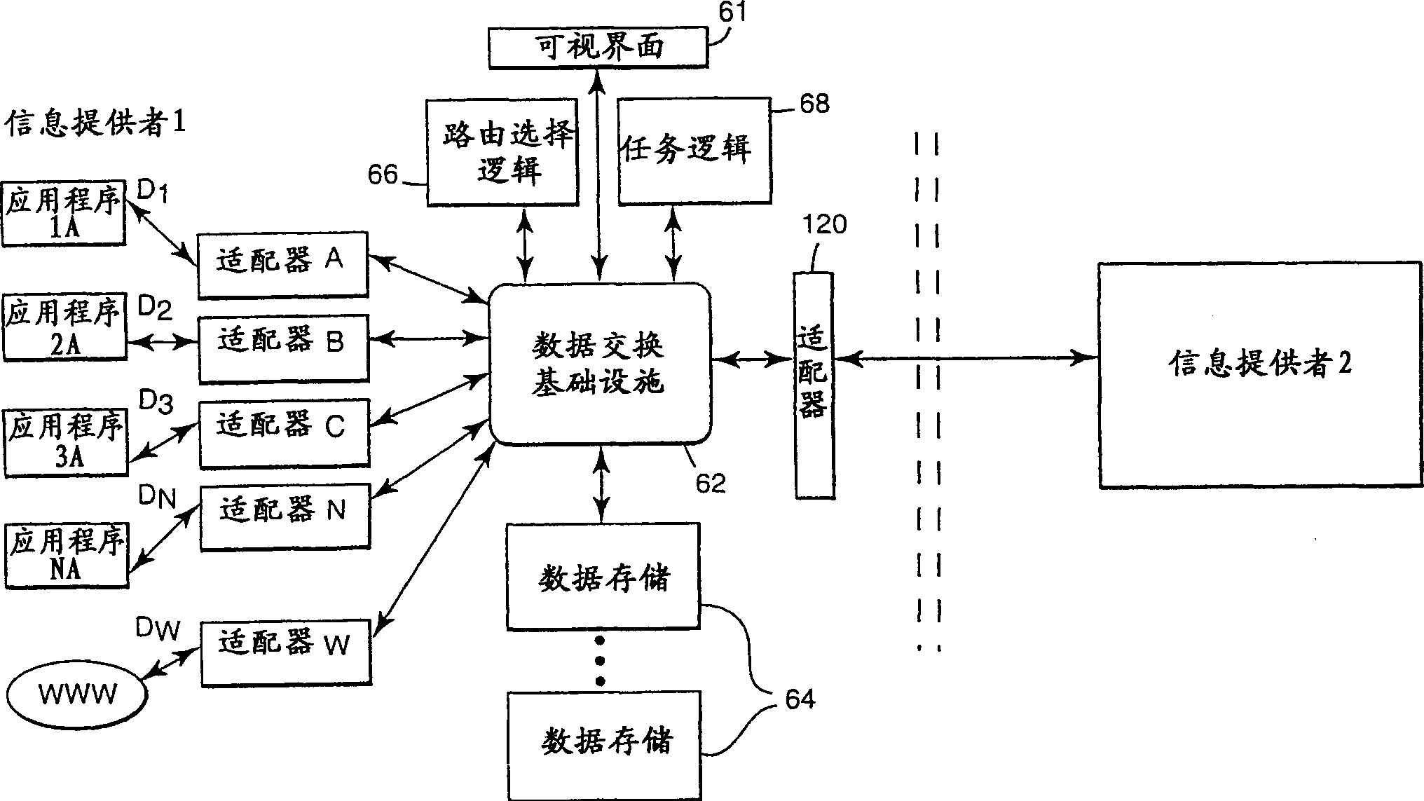
A visual data integration system architecture and methodology is disclosed. The system architecture includes a transport framework that represents a technology-independent integration mechanism that facilitates the exchange of technology-dependent data between disparate applications. A visual interface facilitates the design, deployment, and runtime monitoring of an integrated information system implementation. An integrated information system is developed visually through use of the visual interface by dragging and dropping components within a canvas area of the interface. The components are graphical representations of various telecommunications hardware and software elements, such as information stores, processors, input/output devices and the like. Various components may be packaged together as business extension modules that provide specific business integration capabilities. Interconnections between components are graphically established using a mouse to define sources and destinations of specified data. An underlying configuration/runtime information framework operating above and in concert with the transport framework effectively transforms the graphical interconnections into logical or physical interconnections, which results in the contemporaneous generation of an integrated runtime system. Format neutral data meta-models are employed to model the input and output data requirements of disparate systems and system components so as to remove any cross-dependencies that exist between the systems and technologies implicated in a data integration project. The visual interface enables runtime control and analysis of the business information and system aspects of an integrated system implementation. Visual views onto the live deployment provide consistent management and control for system integrators, business integrators, system managers, and business managers using a single visual interface.

Description

technical field [0001] The present invention generally relates to an information system, and in particular relates to a system and a method for applying a visually integrated interface of different information technologies. Background technique [0002] A number of solutions have been proposed to address the problem of enabling communication between computer system platforms and application programs developed using distinctly different technologies. The need for an improved approach to the design of An integrated information system that can transfer massive amounts of data of different types and formats between applications with dissimilar interface characteristics. [0003] In an attempt to solve the problem of transferring different types of data between dissimilar systems and applications, different data exchange products and methods have been developed. One of the traditional methods of electronically connecting many disparate systems necessitated the establishment of ...

Claims


Application Information

Patent Timeline
Patent Type & Authority Applications(China)
IPC IPC(8): G06F9/44G06F40/143H04L29/06H04L29/08
CPCH04L67/36G06F17/2264G06F8/34H04L69/08H04L69/329H04L67/28G06F17/2247H04L29/06H04L67/2823G06F40/151G06F40/143H04L67/565H04L67/56H04L67/75H04L9/40
Inventor 尼古拉斯·C·谢尔德劳伦斯·菲谢理查德·W·马修斯海马宾杜·格拉胡麒麟温迪·J·郑博伊尔·Y·牟
Owner ADC TELECOMMUNICATIONS
Why Eureka
Try Eureka