Supercharge Your Innovation With Domain-Expert AI Agents!

Lighting device

A technology for lighting devices and optical units, which is applied to lighting devices, lighting device parts, lighting and heating equipment, etc., can solve the problems of complicated assembly operations, complicated configuration space and assembly operations, and enlarged overall shape of the optical system.

Inactive Publication Date: 2007-03-21
CANON KK
View PDF5 Cites 5 Cited by
  • Summary
  • Abstract
  • Description
  • Claims
  • Application Information

AI Technical Summary

Problems solved by technology

[0007] However, in the illuminating device constituted in this way, there are three optical components required for converging and diffusing the illumination light, the number of components increases, and the shape of the optical prism used to constitute the converging optical system is enlarged, so that the optical system as a whole Issues such as larger shape and complicated assembly work due to the high positional accuracy required for their arrangement via many optical components
[0008] In this way, there are problems such as arrangement space and complicated assembly work in the existing converging optical system, and it is difficult to construct an optical system that can realize miniaturization without deteriorating optical characteristics.

Method used


Image

  • Lighting device
  • Lighting device
  • Lighting device

Examples


Embodiment Construction

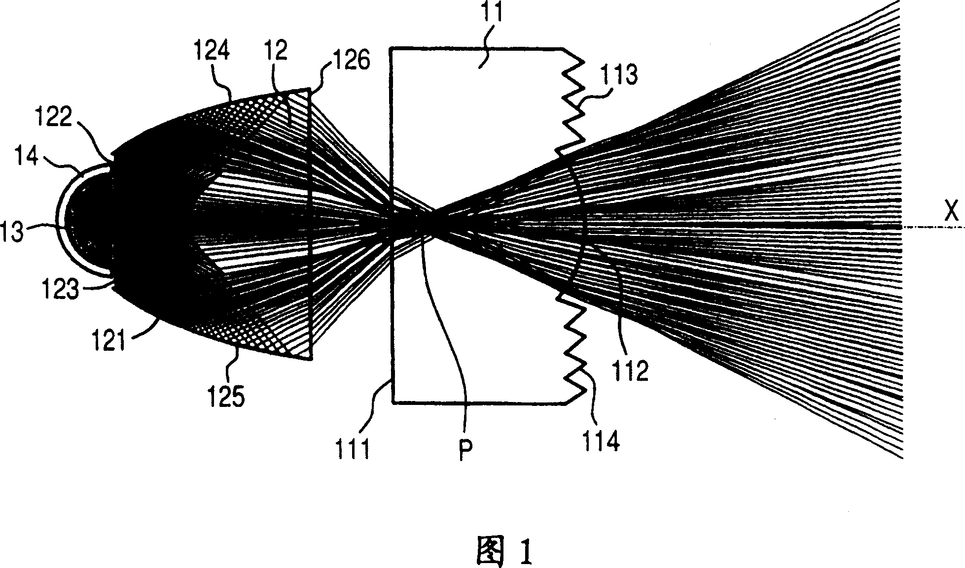
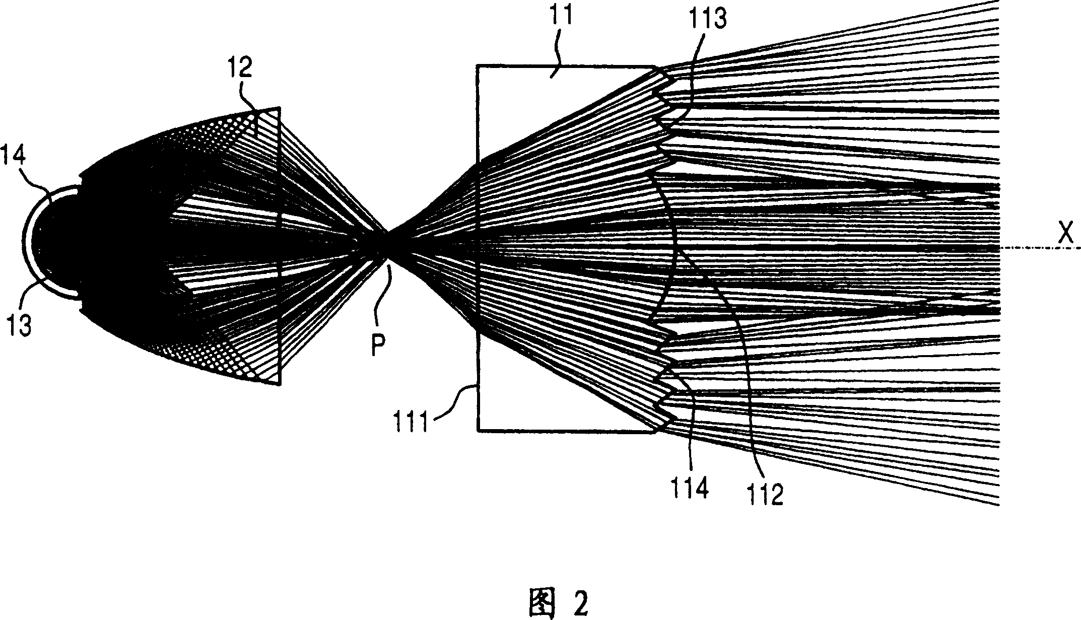
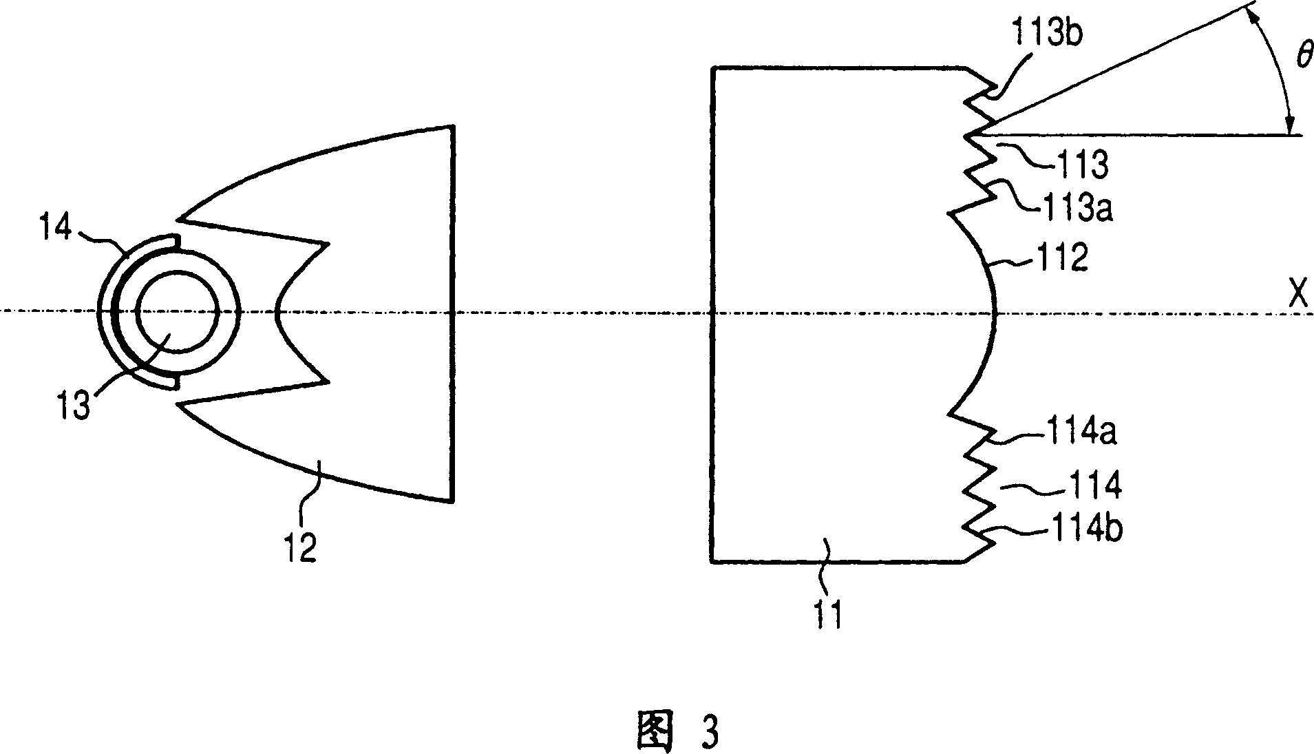
[0042] 1 to 14 show the configuration of a strobe device (illumination device) as an embodiment of the present invention and a camera (photography device) equipped with the strobe device. 1 to 6 are longitudinal cross-sectional views (sections including the radial direction of the light source) of the optical system of the above-mentioned strobe device. 7 and 8 are horizontal cross-sectional views (sections including the central axis in the longitudinal direction of the light source) of the optical system of the strobe device, and FIG. 9 is a longitudinal sectional view showing part of the optical system of the strobe device.

[0043] 10 is an exploded perspective view showing the internal structure of the camera equipped with the strobe unit, and FIGS. 11 and 12 are perspective views showing the assembled state of the strobe unit. Furthermore, FIG. 13 and FIG. 14 are perspective views showing the internal structure of the camera in an assembled state.

[0044] Here, in FIG. ...


PUM


Abstract

An illuminating apparatus having a light source, an optical unit disposed on the object side of the light source having a lens portion having positive refractive power in the central portion thereof, incidence surfaces on which light from the light source is incident and reflecting surfaces for totally reflecting the incident light, on both sides of the lens portion, and an emergence surface from which the light reflected by the reflecting surfaces emerges, wherein a beam emerging from the lens portion and a beam emerging from the emergence surface intersect with each other substantially at the same place in their condensed state, and a second optical unit having a plurality of prism portions, wherein the relative interval between the optical unit and the second optical unit are changed to vary an irradiation angle.

Description

technical field [0001] The present invention relates to the improvement of the optical characteristics of an illuminating device, particularly an illuminating device having a narrow opening area, and a photographing device equipped with the illuminating device. Background technique [0002] Regarding lighting devices used in imaging devices such as cameras, various proposals have been made so far in order to efficiently converge light beams in various directions emitted from a light source within a desired angle of view of an illumination screen. In particular, in recent years, it has been proposed to replace the existing Fresnel lens arranged in front of the light source, and to arrange optical components utilizing total reflection such as prisms and light guides to achieve improved light collection efficiency and miniaturization. [0003] On the other hand, in a fixed-irradiation-range lighting device, along with high-magnification zooming of an imaging device, an unnecess...

Claims


Application Information

Patent Timeline
Patent Type & Authority Patents(China)
IPC IPC(8): G03B15/02G02B3/06F21V5/04G02B27/00G03B30/00
CPCG03B2215/0592G03B15/05G03B2215/0507G02B19/0028G02B19/00G02B19/0047F21V5/045
Inventor 天明良治
Owner CANON KK
Features
  • R&D
  • Intellectual Property
  • Life Sciences
  • Materials
  • Tech Scout
  • Unparalleled Data Quality
  • Higher Quality Content
  • 60% Fewer Hallucinations
Learn More